


Page 42
1998-2006 Edition
NOTE
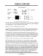
After the 12 minute startup cycle, if the thermostat is in the "ON" position and if the control board
determines that the stove has warmed up, the fuel feed control knob can be turned to adjust the fuel feed
rate and the convection blower speed.
If the control board determines that the stove did not warm up sufficiently by the end of the 12 minute
startup cycle, the fuel feed will be turned OFF and an error code will be flashed using the green STATUS
light on the control panel. The green light will flash once every 2 seconds indicating this error status. If you
encounter this error signal, turn the Main Power Switch to OFF then back to ON to reset the control board.
the position of the fuel feed control knob for 5 minutes after the thermostat turns to OFF. After these 5
minutes, the convection blower speed will be lowered to a speed equivalent to the #1 position of the Fuel
Feed Rate Control Knob.
Caution
In Semiautomatic Mode, when the thermostat turns to the "OFF" position, the fuel feed rate will automatically
drop down to the #1 setting of the Fuel Feed Knob. The fuel feed does not stop. The draft setting, however,
remains where it was set initially. Therefore, if the unit is connected to a wall thermostat, in order to achieve
maximum combustion efficiency at both the higher feed rate and the default low feed rate, the Draft Knob needs
to be set at one position which allows enough combustion air for burning at both the high burn and the low burn.
This means that you will only be able to set the fuel feed knob at a maximum of about 4 to 4-1/2 because one
draft knob setting must provide enough air to burn the pellets efficiently at two fuel feed knob settings.
Furthermore, the Draft Setting must not be turned up so high that it blows the flame out on the lowest (#1) Fuel
Feed Knob setting.
NOTE: A different burn and flame characteristic will be observed when using a 5/16" (8mm) diameter pellet
vs. a 1/4" (6.35mm) diameter pellet. An adjustment to the draft knob setting may be required when switching
from one brand of pellets to another.
NOTE: Should you feel that the air and fuel adjustments are improper or you just cannot seem to provide
enough air to burn efficiently at any fuel feed control knob setting, first check the Trouble Shooting Guide and
the Periodic Maintenance Requirements section of this manual. If a remedy cannot be found, consult your
local Dealer.
Summary of Contents for J1000B
Page 2: ......
Page 8: ...Page vi 1998 2006 Edition ...
Page 16: ...Page 8 1998 2006 Edition ...
Page 20: ...Page 12 1998 2006 Edition ...
Page 36: ...Page 28 1998 2006 Edition ...
Page 44: ...Page 36 1998 2006 Edition ...
Page 45: ...Page 37 1998 2006 Edition ...
Page 46: ...VIII 5 Jamestown Control Panel Page 38 1998 2006 Edition ...
Page 61: ...Page 53 1998 2006 Edition ...
Page 62: ...Page 54 1998 2006 Edition ...
Page 63: ...Page 55 1998 2006 Edition ...
Page 64: ...Page 56 1998 2006 Edition ...
Page 69: ...Page 61 1998 2006 Edition ...
Page 70: ...Page 62 1998 2006 Edition ...
Page 79: ...Appendix A 3 1998 2006 Edition ...
Page 80: ...Appendix A 4 1998 2006 Edition ...
Page 81: ...Appendix A 5 1998 2006 Edition ...
Page 82: ...Appendix A 6 1998 2006 Edition ...
Page 84: ...Appendix B 2 1998 2006 Edition ...
Page 87: ...APPENDIX E AUGER MOTOR BRACKET INSTALLATION Appendix E 1 1998 2006 Edition ...
Page 90: ...Appendix F 3 1998 2006 Edition ...
Page 93: ...APPENDIX H J1000 CROSSFLOW FAN Part 07EEG Appendix H 1 1998 2006 Edition ...
Page 94: ...APPENDIX I 1 EXHAUST BLOWER ASSEMBLY MODEL J1000 Appendix I 1 1998 2006 Edition ...


