


VIII.8 STARTING A FIRE FOR THE FIRST TIME Automatic and
Semiautomatic Modes
Page 43
1998-2006 Edition
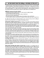
Read the section labeled "Introduction to the Control Panel" before attempting to light a fire.
1. Open the fuel hopper lid and check to make sure that no foreign objects, other than wood pellets, are
present inside the hopper. Small quantities of wood pellets may be left in the hopper after the quality
assurance tests performed at the factory or at your Dealer's warehouse.
2. Fill the hopper with 1/4" (6.35mm) diameter pellets.
3. Open the cast iron door and verify that the firepot is seated properly. CAUTION: It is of the utmost
importance that the firepot be seated properly and aligned exactly with the automatic ignition device tube as
shown in the section labeled "Firepot Placement and Alignment". Make sure that the ash pan is closed
tightly and latched. Check around the perimeter of the ash pan gasket to make sure that the gasket is
seating firmly against the stove face. If you see any gaps, turn the two ash pan latches clockwise to close
the gap and tighten the gasket. Similarly, close and latch the cast iron door tightly.
4. Connect the three prong plug at the end of the stove's power cord to a three prong grounded wall outlet.
CAUTION: This stove must be properly grounded at all times. Do not connect the power supply cord to a
wall switched outlet. Never disconnect the power supply cord in order to turn off this pellet stove. Always
use the ON/OFF switch that is installed in this unit.
5. Push the Main Power ON/OFF Switch to the "ON" position. The green POWER ON indicator light will
illuminate.
6. Turn the Fuel Feed Control Knob clockwise to a setting of "6".
7. Turn the Draft Control Knob to "3".
8. Turn the Wall Thermostat to the ON position. The orange IGNITOR ON indicator light will illuminate and
the red FUEL ON indicator light will flash on and off. Since the fuel feed auger system is most likely empty,
it may take up to 7 minutes before you see any pellets dropping into the firepot. NOTE: The only time you
need to "prime" the auger with fuel is when the stove has run out of fuel or when you are starting the stove
for the very first time. When you see pellets start to drop into the firepot, turn the wall thermostat to the
"OFF" position and wait for 5 minutes.
Warning
Do not use flammable liquids such as gasoline or lighter fluid or any type of fire starter materials to start a fire
in your stove.
9. If the control board is set to run in Automatic Mode, after 5 minutes turn the wall thermostat to the "ON" position.
The 12 minute startup cycle will begin. The orange IGNITOR ON indicator light will illuminate and the red FUEL
ON indicator light will flash on and off. Pellets will start to drop into the firepot. Verify the fuel feed rate by counting
the number of seconds the red FUEL ON Indicator light stays ON and also the number of seconds it stays OFF.
See Auger Run Times in Section X.
10. If the control board is set to run in Semiautomatic Mode, after 5 minutes turn the Main Power switch OFF then
ON. Turn the wall thermostat to the ON position. The 12 minute startup cycle will begin. The orange IGNITOR ON
indicator light will illuminate and the red FUEL ON indicator light will flash on and off. Pellets will start to drop into
the firepot. Verify the fuel feed rate by counting the number of seconds the red FUEL ON indicator light stays ON
and also the number of seconds it stays OFF. See Auger Run Times in Section X.
11. The orange IGNITOR ON indicator light will remain lit for 5 minutes. The pellets in the firepot must ignite and
Summary of Contents for J1000B
Page 2: ......
Page 8: ...Page vi 1998 2006 Edition ...
Page 16: ...Page 8 1998 2006 Edition ...
Page 20: ...Page 12 1998 2006 Edition ...
Page 36: ...Page 28 1998 2006 Edition ...
Page 44: ...Page 36 1998 2006 Edition ...
Page 45: ...Page 37 1998 2006 Edition ...
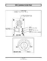
Page 46: ...VIII 5 Jamestown Control Panel Page 38 1998 2006 Edition ...
Page 61: ...Page 53 1998 2006 Edition ...
Page 62: ...Page 54 1998 2006 Edition ...
Page 63: ...Page 55 1998 2006 Edition ...
Page 64: ...Page 56 1998 2006 Edition ...
Page 69: ...Page 61 1998 2006 Edition ...
Page 70: ...Page 62 1998 2006 Edition ...
Page 79: ...Appendix A 3 1998 2006 Edition ...
Page 80: ...Appendix A 4 1998 2006 Edition ...
Page 81: ...Appendix A 5 1998 2006 Edition ...
Page 82: ...Appendix A 6 1998 2006 Edition ...
Page 84: ...Appendix B 2 1998 2006 Edition ...
Page 87: ...APPENDIX E AUGER MOTOR BRACKET INSTALLATION Appendix E 1 1998 2006 Edition ...
Page 90: ...Appendix F 3 1998 2006 Edition ...
Page 93: ...APPENDIX H J1000 CROSSFLOW FAN Part 07EEG Appendix H 1 1998 2006 Edition ...
Page 94: ...APPENDIX I 1 EXHAUST BLOWER ASSEMBLY MODEL J1000 Appendix I 1 1998 2006 Edition ...


