


VIII.10 TURNING OFF THE STOVE
Page 46
1998-2006 Edition
AUTOMATIC MODE
To temporarily stop the stove from outputting heat into the home, turn the wall thermostat to the OFF position. The
fuel will stop feeding instantly. However, the convection air blower will continue to run for 5 minutes at the speed it
was running at immediately before the wall thermostat was turned to OFF. To permanently stop the stove from
running, wait 20 minutes after the thermostat is turned to OFF then turn the main power switch to the OFF position.
Once the stove cools down sufficiently, all motors will stop functioning.
Warning
Do not turn the main power ON/OFF switch to the OFF position while there are pellets burning in the firepot or
while the stove is hot.
SEMIAUTOMATIC MODE
Turn the wall thermostat to the OFF position. The fuel feed rate will decrease to the idle feed instantly. However,
the convection air blower will continue to run for 5 minutes at the speed it was running at immediately before the
wall thermostat was turned to OFF. Let the stove run in idle mode for 10 minutes then turn the main power switch
to the OFF position. Once the stove cools down sufficiently, all motors will stop functioning.
MANUAL MODE
Turn the Wall Switch to the OFF position. Let the stove run at this rate for 20 minutes. Turn the main power switch
to the OFF position. Once the stove cools down sufficiently, all motors will stop functioning.
POWER OUTAGE
In the event of a brown-out, power outage or interruption of electrical power to the stove, the entire system will shut
down; possibly causing sporadic wisps of smoke to escape from the window airwash system temporarily.
When set to run in the Automatic or Semiautomatic modes, if electrical power to the control board is interrupted for
any reason and then restored, the startup cycle will be initiated if the wall thermostat is in the ON position or if in
the OFF position, the startup cycle will be initiated the next time the wall thermostat calls for heat.
When set to run in the Manual mode, if electrical power to the control board is interrupted for any reason and then
restored, the startup cycle will be initiated as soon as the power is restored.
Warning
Never unplug the power cord or disrupt the power supply in any way while the stove is in operation. Doing so will cause
small amounts of exhaust gases and soot particles to leak into the home causing smoke and soot damage.
Caution
During a power outage, do not open the cast iron door. Opening the door can cause excessive smoke and soot
particles to be emitted into the home causing smoke and soot damage.
Jamestown Recommends the use of a Power Inverter
If brown-outs and power outages are common in your area, Jamestown recommends that a power inverter be
employed to power the pellet stove during these conditions. A power inverter is an electronic device that converts
DC power (stored in batteries) to AC power (similar to the home electrical supply and required by all Jamestown
pellet stoves for normal operation). The length of time that the pellet stove will function normally, when employing
a power inverter, depends on the capacity of the battery coupled with the power inverter.
When purchasing a power inverter, verify the following information to ensure that the appropriate model is selected.
Power Inverter Requirement Specifications:
Output 120 Volts, 60 Hertz, 8 Amps, 800 Watts Minimum Continuous Output
Summary of Contents for J1000B
Page 2: ......
Page 8: ...Page vi 1998 2006 Edition ...
Page 16: ...Page 8 1998 2006 Edition ...
Page 20: ...Page 12 1998 2006 Edition ...
Page 36: ...Page 28 1998 2006 Edition ...
Page 44: ...Page 36 1998 2006 Edition ...
Page 45: ...Page 37 1998 2006 Edition ...
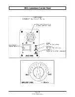
Page 46: ...VIII 5 Jamestown Control Panel Page 38 1998 2006 Edition ...
Page 61: ...Page 53 1998 2006 Edition ...
Page 62: ...Page 54 1998 2006 Edition ...
Page 63: ...Page 55 1998 2006 Edition ...
Page 64: ...Page 56 1998 2006 Edition ...
Page 69: ...Page 61 1998 2006 Edition ...
Page 70: ...Page 62 1998 2006 Edition ...
Page 79: ...Appendix A 3 1998 2006 Edition ...
Page 80: ...Appendix A 4 1998 2006 Edition ...
Page 81: ...Appendix A 5 1998 2006 Edition ...
Page 82: ...Appendix A 6 1998 2006 Edition ...
Page 84: ...Appendix B 2 1998 2006 Edition ...
Page 87: ...APPENDIX E AUGER MOTOR BRACKET INSTALLATION Appendix E 1 1998 2006 Edition ...
Page 90: ...Appendix F 3 1998 2006 Edition ...
Page 93: ...APPENDIX H J1000 CROSSFLOW FAN Part 07EEG Appendix H 1 1998 2006 Edition ...
Page 94: ...APPENDIX I 1 EXHAUST BLOWER ASSEMBLY MODEL J1000 Appendix I 1 1998 2006 Edition ...