


1. EVERY TIME BEFORE YOU LIGHT A FIRE
2. ONCE OR TWICE A WEEK
Page 48
1998-2006 Edition
Every time that the fire in the stove needs to be re-lit, perform the following simple cleanings:
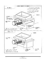
FIREPOT/ BURN GRATE: Inspect for accumulation of clinkers inside the firepot and clean. Be sure to inspect the
air inlet holes (in firepot) to make sure they are clear of ash. Fit the firepot properly on the firepot base when
replacing (See Figure C1). After cleaning and each time the firepot is replaced, the firepot must be seated properly.
The outer edges of the firepot underside have been machined to fit properly with the machined top edge of the
firepot base. Make sure that these two edges meet properly and that there is no ash or other debris between them.
An improper or a poor seal between the firepot and the firepot base will yield a lazy burn which will deposit soot on
the glass and firebox walls and will result in drastically low combustion efficiency.
FIREPOT BASE: This is the "empty box" on which the firepot rests. If ash or other debris have accumulated inside
the firepot base, clean completely using a vacuum hose attachment.
AIR WASH BRACKET: See Figure C2. This is the metal bracket that is located along the interior bottom edge of
the door glass. Using a vacuum hose attachment, clean ash deposits from this bracket.
Perform the following cleanings every 3 to 4 days.
FIREBOX AREA: There will be some ash buildup to the side, front and above the insulative brick pattern board.
Remove the ash deposits by using a vacuum cleaner with a hose attachment. The brick pattern boards are fragile.
Be very gentle with them. Do not scrub.
HEAT EXCHANGER TUBES: See Figure C3. Do not touch the scraper rods when the stove is hot. The heat
exchanger tubes will collect fly ash overtime. Three scrapers attached to rods (only one scraper rod on J1000B)
protruding through the front face of the stove (above the door) permits these tubes to be scraped clean. Keep the
stove door closed when scraping the tubes. Pull each scraper rod outward, as far as it travels, and push it back to
its original position, repeatedly. When ash no longer falls when the scraper rod is pulled or pushed, the heat
exchanger tubes are clean. After cleaning, push the rods completely inward to avoid warping the scraper during
normal operation of the stove.
ASH PAN: Open the ashpan only after the stove is cool and all the embers have been extinguished. Remove by
turning the two knobs on the front of the ash pan counter-clockwise and pulling the pan forward. Empty the ash
into a non-combustible container with an air-tight lid. Dispose of the ash after all the embers have cooled thoroughly.
When replacing the ash pan, make certain that the gasket around the perimeter of the ashpan face creates a tight
seal with the firebox face when the ashpan latches are locked.
UPPER SHELVES: See Figure C4. Insert the bottle brush between the heat exchange tubes and the firebox on
each side of the firebox and work the brush in all directions. This will clear a 3/4" (19mm) shelf where fly ash builds
up. Brush in between the heat exchange tubes. Remove the trivet on the top of the stove and tap gently on the top
underneath the trivet until all fly ash has dropped. Vacuum the inside of the firebox.
FRAGILE, HANDLE WITH CARE
The Brick Pattern Boards Are Fragile!
When cleaning, remember that the brick pattern boards are very fragile. Do not use a wire brush or any
other object to scrape ash off the brick pattern boards. If soot has deposited on the boards, burn off the
deposit by using a hand held propane torch. Hold the flame on one area of the board until the board
surface glows bright red and slowly move the flame across the surface of the board.
Summary of Contents for J1000B
Page 2: ......
Page 8: ...Page vi 1998 2006 Edition ...
Page 16: ...Page 8 1998 2006 Edition ...
Page 20: ...Page 12 1998 2006 Edition ...
Page 36: ...Page 28 1998 2006 Edition ...
Page 44: ...Page 36 1998 2006 Edition ...
Page 45: ...Page 37 1998 2006 Edition ...
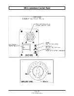
Page 46: ...VIII 5 Jamestown Control Panel Page 38 1998 2006 Edition ...
Page 61: ...Page 53 1998 2006 Edition ...
Page 62: ...Page 54 1998 2006 Edition ...
Page 63: ...Page 55 1998 2006 Edition ...
Page 64: ...Page 56 1998 2006 Edition ...
Page 69: ...Page 61 1998 2006 Edition ...
Page 70: ...Page 62 1998 2006 Edition ...
Page 79: ...Appendix A 3 1998 2006 Edition ...
Page 80: ...Appendix A 4 1998 2006 Edition ...
Page 81: ...Appendix A 5 1998 2006 Edition ...
Page 82: ...Appendix A 6 1998 2006 Edition ...
Page 84: ...Appendix B 2 1998 2006 Edition ...
Page 87: ...APPENDIX E AUGER MOTOR BRACKET INSTALLATION Appendix E 1 1998 2006 Edition ...
Page 90: ...Appendix F 3 1998 2006 Edition ...
Page 93: ...APPENDIX H J1000 CROSSFLOW FAN Part 07EEG Appendix H 1 1998 2006 Edition ...
Page 94: ...APPENDIX I 1 EXHAUST BLOWER ASSEMBLY MODEL J1000 Appendix I 1 1998 2006 Edition ...


