


3. AFTER EVERY ONE TON (909kg or 40 BAGS) OF PELLETS
Page 49
1998-2006 Edition
The Exhaust Channels, Heat Exchangers and Vent System will collect fly ash over time. Fly ash that deposits
in these exhaust pathways reduces the flow of exhaust gases out of the system. If exhaust gas flow out of the
system is reduced, combustion air flow into the firepot will also be reduced. This can lead to lazy burns and
low combustion efficiency. It is critical that these exhaust pathways be cleaned periodically. Jamestown
recommends that all the areas listed below be cleaned, as stated, after every ton of pellets burned.
IMPORTANT Cleaning the through the Wall Kit
- We suggest cleaning your through the wall kit on or before every ton (909kg) of pellets.
- Do not take apart your through the wall kit.
- The pipe is cleaned from the exhaust outside, using your cleaning kit.
- Take Rodent cap off by pulling straight off.
- Using your long brush, insert into stovepipe until you feel resistance. Clean out all build up.
- On a 45º through the wall kit, you will need a 45º through the wall cleaning kit that contains a longer brush.
We highly recommend hiring your Jamestown Dealer to service your stove after your first ton (909kg) of
pellets burned to properly train you in cleaning and maintaining your stove.
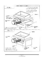
SIDE EXHAUST CHANNELS (All Pellet Stoves): See Figure C4. Access Plates to the Side Exhaust Channels
are located on both sides of the interior of the firebox. On J2000T and J2001T model stoves, the Side Exhaust
Channel Access Plates are located behind the side Brick Pattern Boards. It is necessary to remove the side
Brick Pattern Boards before the Side Exhaust Channel access plates can be removed. See Figure C4.
To remove the Brick Pattern Board, use a 5/16" Hex Driver to loosen the screw that holds the Side Brick Pattern
Board retainer bracket in place. Carefully lift the front end of the retainer bracket upward and remove. Carefully
remove the Side Brick Pattern Board from the firebox.
Using a 5/16" Hex Driver, loosen (do not remove) the single screw that holds the Side Exhaust Channel
Access Plate in place. Lift the Access Plate upward until the larger opening in the key hole aligns with the
screw head. Pull the Access Plate outward and remove. On the inner wall of the Exhaust Channel, you will
find a smaller Access Plate that is shaped similar to the one you just removed. This plate provides access
to the Inner Exhaust Channel. Remove this Access Plate using the same method you used to remove the
outer Access Plate.
Using a flash light, look inside the Side Exhaust Channels. If you see excessive soot or creosote deposits, it may
be necessary to remove the Exhaust Blower assembly and clean the impeller blades to prevent damage to the
Blower Motor. Please note that excessive soot deposit means that the Manual Draft setting was too low and
excessive creosote deposit means that the Manual Draft setting was too high. Adjust the Manual Draft setting
accordingly for future burns.
Using a bottle brush, clean all surfaces you can reach in each compartment. It is important to work the bottle
brush in all directions. Lightly tap the walls of the inside walls of the ash compartment and the inside walls of
the firebox. Continue to tap until you can no longer see any fly ash drop. Thoroughly vacuum out these
compartments using a vacuum cleaner with a hose attachment (use the hose attachment from the JR004T
Cleaning Kit). Replace the Access Plates and the side Brick Pattern Boards as before making certain that the
plates create a tight seal.
REAR EXHAUST CHANNEL (Model J2000T and J2001T Only): See Figure C4. Very Carefully, remove the
brick pattern boards on both sides and back of the firebox by first loosening the screw in the bracket at the top
of each brick board, sliding the bracket out and then lifting the board out of the firebox. The Rear Exhaust
Channel Access Plate is located on the back of the firebox towards the left side. Remove this Access Plate.
Using a flash light, look inside the Rear Exhaust Channel. If you see excessive soot or creosote deposits, it may
be necessary to remove the Exhaust Blower assembly and clean the impeller blades to prevent damage to the
Blower Motor. Please note that excessive soot deposit means that the Manual Draft setting was too low and
excessive creosote deposit means that the Manual Draft setting was too high. Adjust the Manual Draft setting
accordingly for future burns.
Summary of Contents for J1000B
Page 2: ......
Page 8: ...Page vi 1998 2006 Edition ...
Page 16: ...Page 8 1998 2006 Edition ...
Page 20: ...Page 12 1998 2006 Edition ...
Page 36: ...Page 28 1998 2006 Edition ...
Page 44: ...Page 36 1998 2006 Edition ...
Page 45: ...Page 37 1998 2006 Edition ...
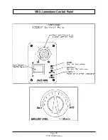
Page 46: ...VIII 5 Jamestown Control Panel Page 38 1998 2006 Edition ...
Page 61: ...Page 53 1998 2006 Edition ...
Page 62: ...Page 54 1998 2006 Edition ...
Page 63: ...Page 55 1998 2006 Edition ...
Page 64: ...Page 56 1998 2006 Edition ...
Page 69: ...Page 61 1998 2006 Edition ...
Page 70: ...Page 62 1998 2006 Edition ...
Page 79: ...Appendix A 3 1998 2006 Edition ...
Page 80: ...Appendix A 4 1998 2006 Edition ...
Page 81: ...Appendix A 5 1998 2006 Edition ...
Page 82: ...Appendix A 6 1998 2006 Edition ...
Page 84: ...Appendix B 2 1998 2006 Edition ...
Page 87: ...APPENDIX E AUGER MOTOR BRACKET INSTALLATION Appendix E 1 1998 2006 Edition ...
Page 90: ...Appendix F 3 1998 2006 Edition ...
Page 93: ...APPENDIX H J1000 CROSSFLOW FAN Part 07EEG Appendix H 1 1998 2006 Edition ...
Page 94: ...APPENDIX I 1 EXHAUST BLOWER ASSEMBLY MODEL J1000 Appendix I 1 1998 2006 Edition ...


