


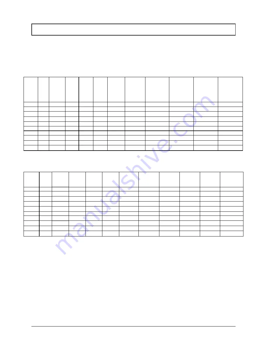
CONTROL BOARD PROGRAM PARAMETERS TABLES
Page 58
1998-2006 Edition
The control board uses the parameters in the following tables from the Row # that corresponds to the
selector switch position. The tables below list the various parameters specific to each model. When
changing the program, please refer to the table that is specific to the model of stove you purchased.
TABLE X1: J1OOOB PROGRAM PARAMETERS
Program
selector
switch #
Mode
High Fuel
ON Time
(Sec)
High
Fuel
OFF
Time
(Sec)
Low Fuel
ON Time
(Sec)
Low Fuel
OFF
Time
(Sec)
Convection
Blower Low
Limit
Voltage
(Volts AC)
Convection
Blower High
Limit Voltage
(Volts AC)
STARTUP
CYCLE
TOTAL LENGTH
(Min)
STARTUP
CYCLE
Heater ON Time
(Min)
STARTUP
CYCLE
Fuel ON Time
(Sec)
STARTUP
CYCLE
Fuel OFF Time
(Sec)
0
Auto
6
4
2.5
7.5
100
120
12
5
3
7
1
Auto
6
4
2.5
7.5
105
120
12
5
3
7
2
Auto
6
4
2.5
7.5
100
120
12
5
3.5
6.5
3
Auto
6
4
3
7105
120
12
5
3.5
6.5
4
Auto
5.5
4.5
3
7105
120
12
5
3
7
5
Semi
6
4
2.5
7.5
100
120
12
5
3
7
7
Semi
6
4
2.5
7.5
105
120
12
5
3
7
8
Semi
6
4
2.5
7.5
100
120
12
5
3.5
6.5
8
Semi
6
4
3
7
105
120
12
5
3.5
6.5
9
Semi
5.5
4.5
3
7
105
120
12
5
3
7
TABLE X2:
J2000T and J2001T PROGRAM PARAMETERS
Program
selector
switch #
Mode
High Fuel
ON
Time (Sec)
High Fuel
OFF Time
(Sec)
Low Fuel
ON
Time
(Sec)
Low Fuel
OFF Time
(Sec)
Convection
Blower Low
Limit Voltage
(Volts AC)
Convection
Blower High
Limit Voltage
(Volts AC)
STARTUP
CYCLE
TOTAL
LENGTH (Min)
STARTUP
CYCLE
Heater
ON Time (Min)
STARTUP
CYCLE Fuel
ON Time
(Sec)
STARTUP
CYCLE
Fuel OFF Time
(Sec)
0
Auto
7.5
2.5
25
7.5
100
120
12
5
3
7
1
Auto
7.5
2.5
2.5
7.5
105
120
12
5
3
7
2
Auto
7.5
2.5
2.5
7.5
100
120
12
5
3.5
6.5
3
Auto
7.5
2.5
3
7
105
120
12
5
3.5
6.5
4
Auto
6.7
3.3
3
7
105
120
12
5
3
7
5
Semi
7.5
2.5
2.5
7.5
100
120
12
5
3
7
6
Semi
7.5
2.5
2.5
7.5
105
120
12
5
3
7
7
Semi
7.5
2.5
2.5
7.5
100
120
12
5
3.5
6.5
8
Semi
7.5
2.5
3
7
105
120
12
5
3.5
6.5
9
Semi
6.7
3.3
3
7
105
120
12
5
3
7
Summary of Contents for J1000B
Page 2: ......
Page 8: ...Page vi 1998 2006 Edition ...
Page 16: ...Page 8 1998 2006 Edition ...
Page 20: ...Page 12 1998 2006 Edition ...
Page 36: ...Page 28 1998 2006 Edition ...
Page 44: ...Page 36 1998 2006 Edition ...
Page 45: ...Page 37 1998 2006 Edition ...
Page 46: ...VIII 5 Jamestown Control Panel Page 38 1998 2006 Edition ...
Page 61: ...Page 53 1998 2006 Edition ...
Page 62: ...Page 54 1998 2006 Edition ...
Page 63: ...Page 55 1998 2006 Edition ...
Page 64: ...Page 56 1998 2006 Edition ...
Page 69: ...Page 61 1998 2006 Edition ...
Page 70: ...Page 62 1998 2006 Edition ...
Page 79: ...Appendix A 3 1998 2006 Edition ...
Page 80: ...Appendix A 4 1998 2006 Edition ...
Page 81: ...Appendix A 5 1998 2006 Edition ...
Page 82: ...Appendix A 6 1998 2006 Edition ...
Page 84: ...Appendix B 2 1998 2006 Edition ...
Page 87: ...APPENDIX E AUGER MOTOR BRACKET INSTALLATION Appendix E 1 1998 2006 Edition ...
Page 90: ...Appendix F 3 1998 2006 Edition ...
Page 93: ...APPENDIX H J1000 CROSSFLOW FAN Part 07EEG Appendix H 1 1998 2006 Edition ...
Page 94: ...APPENDIX I 1 EXHAUST BLOWER ASSEMBLY MODEL J1000 Appendix I 1 1998 2006 Edition ...


