


PROGRAM SELECTION INFORMATION FOR ALL STOVE MODELS
DEFINITIONS OF THE THREE CONTROL MODES
Page 59
1998-2006 Edition
Selector Switch positions numbered 0 through 4 will cause the microprocessor to run in the Automatic Mode
if the stove is connected to a wall thermostat and in the Manual Mode if connected to a wall switch. Selector
switch positions numbered 5 through 9 will cause the microprocessor to run in the semiautomatic mode.
Please note that the parameters in the #0 position are identical to those in the #5 position. The parameters
in the #1 position are identical to those in the #6 position and so on.
Positions #0 and #5 provide parameters for ideal and normal conditions.
Positions #1 and #6 provide parameters for rural areas that are subject to low line voltage situations. The
microprocessor calculates the convection low limit voltage based on a line voltage of 120 VAC. During low
voltage situations, the Convection Blower Low Voltage Limit causes the blower to turn too slowly during low
burn. Since this condition promotes frequent overheating of the stove, the convection blower circuit low limit
voltage has been increased to allow higher convection blower speeds during low burn.
Positions #2 and #7 provide parameters for conditions in which the stove does not warm up sufficiently
during the 12 minute startup cycle. For these situations, the fuel feed rate for the 12 minute startup cycle
has been increased. This increased fuel feed rate during the startup cycle will guarantee that the stove
warms up sufficiently by the end of the 12 minute startup cycle.
Positions #3 and #8 provide parameters for conditions where during low burn, the pellet fuel is consumed
too fast and causes the fire to be extinguished frequently. This is generally a direct result of the pellet fuel
density being too low or, in low altitude installations, too much combustion air being supplied at the lowest
draft setting. For these situations, the fuel feed rate during the low burn periods has been increased. Since
this increase can potentially lead to a overheated unit, the Convection Blower Low Voltage Limit has been
increased as well. Furthermore, the startup cycle fuel feed rate has also been increased to guarantee a
sustained flame during the startup cycle.
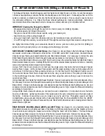
Position #4 and #9 provide parameters for high altitude installations. The maximum fuel feed rate has been
decreased by 10%, the low burn fuel feed rate has been increased by 20% and the startup cycle fuel feed
rate has been increased by 17%.
Automatic Mode: This mode is defined as the mode in which the stove functions similarly to a gas fired
furnace. The wail thermostat or wall switch controls the ON/OFF cycles of the stove and attempts to control
the room air temperature. Once the unit has warmed up, the fuel feed rate can be controlled by turning the
Fuel Feed Control Knob. Though the system is termed "automatic", the combustion air volume must be
controlled using the Manual Draft Control Knob.
Each time the wall thermostat calls for heat, the stove will automatically default to its pre-programmed 12
minute startup cycle. During the startup cycle, the fuel is ignited employing the auto ignition device (which
is included as a standard feature) and the stove is allowed to warm up at a controlled fuel feed rate for 12
minutes.
During the startup cycle, if the control board determines that the stove has warmed up (stove is considered
to be warmed up if the 110ºF (43.3ºC) snap disk thermostat is ON), the convection blower speed will
automatically increase to the setting determined by the position of the Fuel Feed Control Knob. At the end
of the startup cycle, if the 110ºF (43.3ºC) snap disk thermostat is ON, the fuel feed rate will increase to the
setting determined by the position of the Fuel Feed Control Knob. The stove will then continue to run at that
fuel feed rate and convection blower speed until the room temperature reaches the temperature set on the
wall thermostat.
At the end of the 12 minute startup cycle, if the control board determines that the stove did not warm up, the
fuel feed will be shut off and an error code will be flashed using the green light on the control panel. If this
error code is encountered, the Main Power Control Switch must be turned to OFF then to ON to restart the
stove. Toggling the wall thermostat from ON to OFF then to ON will not restart the stove. This is a safety
feature built into the control system and is not a bug. If electrical power to the control board is interrupted
for any reason and then restored, the startup cycle will be initiated if the wall thermostat is in the ON position.
Summary of Contents for J1000B
Page 2: ......
Page 8: ...Page vi 1998 2006 Edition ...
Page 16: ...Page 8 1998 2006 Edition ...
Page 20: ...Page 12 1998 2006 Edition ...
Page 36: ...Page 28 1998 2006 Edition ...
Page 44: ...Page 36 1998 2006 Edition ...
Page 45: ...Page 37 1998 2006 Edition ...
Page 46: ...VIII 5 Jamestown Control Panel Page 38 1998 2006 Edition ...
Page 61: ...Page 53 1998 2006 Edition ...
Page 62: ...Page 54 1998 2006 Edition ...
Page 63: ...Page 55 1998 2006 Edition ...
Page 64: ...Page 56 1998 2006 Edition ...
Page 69: ...Page 61 1998 2006 Edition ...
Page 70: ...Page 62 1998 2006 Edition ...
Page 79: ...Appendix A 3 1998 2006 Edition ...
Page 80: ...Appendix A 4 1998 2006 Edition ...
Page 81: ...Appendix A 5 1998 2006 Edition ...
Page 82: ...Appendix A 6 1998 2006 Edition ...
Page 84: ...Appendix B 2 1998 2006 Edition ...
Page 87: ...APPENDIX E AUGER MOTOR BRACKET INSTALLATION Appendix E 1 1998 2006 Edition ...
Page 90: ...Appendix F 3 1998 2006 Edition ...
Page 93: ...APPENDIX H J1000 CROSSFLOW FAN Part 07EEG Appendix H 1 1998 2006 Edition ...
Page 94: ...APPENDIX I 1 EXHAUST BLOWER ASSEMBLY MODEL J1000 Appendix I 1 1998 2006 Edition ...


