background image

Jamesway Incubation Systems

MANHDS

Revision B

Hatchery Disinfectant Manual

Installation, Operation, Maintenance

and Disinfectant Usage

TM

Summary of Contents for Hatchery Disinfectant System

Page 1: ...Jamesway Incubation Systems MANHDS Revision B Hatchery Disinfectant Manual Installation Operation Maintenance and Disinfectant Usage TM ...

Page 2: ...6 fax 519 624 5803 email for customer service service jamesway com This book and its contents are the property of the Jamesway Incubator Company Inc Reproduction in whole or in part by any means without permission of Jamesway Incubator Company Inc is prohibited 2002 Jamesway Incubator Company Inc ...

Page 3: ...s for Installation 12 Quick Connections 12 Installation in Jamesway Incubators and Hatchers 13 The Multi Stage Incubator 13 The Common Wall Hatcher 13 The PX Hatcher 14 The Single Stage ACI Incubator or Hatcher 15 Operation 16 General 16 The Electronic Controller 16 Programming the Electronic Controller 17 Automated Operation 17 Programming Functions 18 Reviewing the Program 20 Preventative and Co...

Page 4: ...nit Installation Kit 28 Appendix C Organisms and Surface Disinfectants 30 General 30 Bacterial Organisms 30 Viral Organisms 30 Fungal Organisms 30 Protozoal Organisms 30 Chemicals Used for Disinfecting 30 General 30 Cresols and Cresylic Acid 30 Phenols 30 Phenol Coefficient 31 Iodine 31 Chlorine 31 Quaternary Ammonium 31 Glossary 32 Abbreviations 32 ...

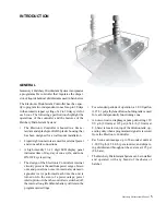
Page 5: ...cle and zone ON OFF cycle setting The design of the Electronic Controller s internal circuitry protects the unit from power surges brown outs and power line noise An internal systems di agnostics test is performed each time the unit is turned on In the event of a power outage power interruption or when the controller is switched off the internal long life lithium battery will retain the programmed...

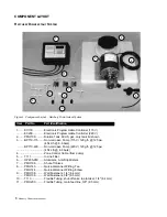
Page 6: ...ars BP710 220 Non corrosive Pump 220 V 120 g h 125 psi 454 L h 8 6 bars 4 Zone Control Cable from pump 5 T111 In line Filter 6 HP205 95C Atomizers Anti Drip Misters 7 PMH106 Shut off Valves 8 PMH143 Quick disconnect Fitting Tee PMH144 Quick disconnect Fitting Elbow 9 PMH108 Wall Fasteners 1 4 6 4 mm PMH138 Wall Fasteners 3 8 9 5 mm 10 T113 Flexible Tubing shut off valve to atomizer 1 4 6 4 mm 11 P...

Page 7: ...nual 7 ELECTRONIC CONTROLLER FEATURES Figure 2 Electronic Controller Features Protective Housing Fire Retardant ABS High Intensity LED Panel Splash Proof Key Pad Power input Cable 115 220 VAC 50 60 Hz Zone 2 Cable Zone 1 Cable ...

Page 8: ...f microorganism present The most common of these organisms can be grouped into four main categories bacterial organisms viral organisms fungal organisms and protozoal organisms Disinfectants should be acquired based on the applica tion and intended use in specific areas of the hatchery seeTable 5 page 24 for a list of disinfectants and their recommended usage Note Jamesway Incubator Company does n...

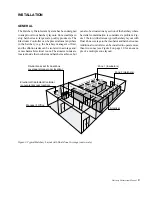
Page 9: ...cubator and hatcher machines but Figure 3 Typical Hatchery Layout with Dual Zone Coverage not to scale can also be situated in any section of the hatchery where bacterial contamination is considered a problem Fig ure 3 below illustrates a typical hatchery layout with Dual Zone coverage to the incubator and hatcher rooms Additional controllers can be installed to operate more than two zones see Fig...

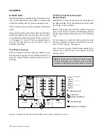
Page 10: ...e g in another room you may consider enclosing the electrical cable in conduit THE ELECTRONIC CONTROLLER AND DILUTION TANKS Establish the location of the electronic controller and the dilution tanks There should be an electrical outlet in vicinity of the controller Ideally both tanks and controller should be located close to each other so that the controller plugs directly into the pump socket wit...

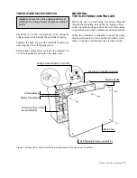
Page 11: ... 5 Voltage Select Switch and Battery Replacement in the Electronic Controller Electronic Controller Housing Back Cover Electronic Time of Day Board EC098 Mounting Tabs Self Tapping Screws quantity 5 Lithium Battery Battery Receptacle Voltage Select Switch 115 220V MOUNTING THE ELECTRONIC CONTROLLER Mount the unit to a wall using two screws threaded through the mounting tabs on the top surface of e...

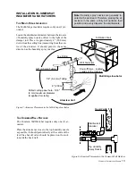
Page 12: ...lows uninterrupted ma chine operation should the disinfectant system require shut off of individual atomizer units see Figure 7 on page 13 Avoid sharp bends in the routing of the 3 8 9 5 mm tubing Minimal use of 90 elbow fittings is recommended With the addition of each elbow there is a corresponding drop in line pressure Cut the tubing to the required lengths using a util ity knife Use the suppli...

Page 13: ... mm down from the ceiling line measuring from the cen tre of the atomizer It should point in the same direction as the humidity spray nozzles Figure 7 Atomizer Placement in the Multi Stage Incubator THE COMMON WALL HATCHER The Common Wall Hatcher requires only one 1 at omizer Place the atomizer as close to the top humidity nozzle as possible It should point directly at the centre of the fan The sh...

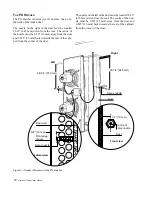
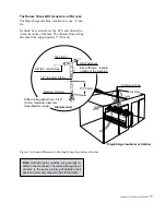
Page 14: ... nozzle on the right of the duct must be located 33 25 845 mm down from the roof The centre of the nozzle must be 0 50 13 mm away from the duct and 0 625 16 mm back towards the rear of the cabi net from the corner of the duct Figure 9 Atomizer Placement in the PX Hatcher The nozzle on the left of the duct must be located 38 25 972 mm down from the roof The centre of the noz zle must be 0 50 13 mm ...

Page 15: ... Air Flow THE SINGLE STAGE ACI INCUBATOR OR HATCHER The Single Stage machine requires only one 1 noz zle It should be centred above the ECU and directed to wards the centre of the fans The distance from ceiling line should be approximately 2 50 mm Figure 10 Atomizer Placement in the Single Stage Incubator or Hatcher Note Humidity spray nozzles are generally lo cated in the air stream Therefore pla...

Page 16: ...d into a wall outlet two or three prong receptacle as available Press the POWER ON OFF switch on the keypad On initial power up the LED panel will display the following information JAMESWAY next message VERSION 1 09 next DISINFECTANT CONTROLLER The controller will then go into operation if there is a program already in memory The unit will then dis play the following 3 30 15 PM 1 OFF 4 ON Note In ...

Page 17: ...X 00 AM Function Controller will turn off output relays Controller enters the operation mode If the unit has a stored program see Table 2 for pro gramming Press the up or down arrow key to change the hour reading Press the up or down arrow key to change the minute reading Notes Turning the controller ON will also activate the ON cycle for both zones If the CLOCK SET key is not pressed at this time...

Page 18: ...down arrow to advance the MINUTES read ing from 00 to 59 The HOUR digits will flash initially Press the up arrow to advance the HOUR reading from 1 00 to 12 00 a m or p m The MINUTES digits will flash ini tially Press the up or down arrow to advance the MINUTES read ing from 00 to 59 minutes Notes Use this step to avoid acciden tal program changes Press SET to lock in Zone The digits can be advanc...

Page 19: ...dvance to the next day until the down arrow NO is pressed See next step See next step The programming will continue with the next day in the sequence e g step 4 in this sequence Notes As the arrow key is pressed and held the SECONDS digits will advance or back up slowly at first and then move at a higher rate To eliminate or skip a day set the TIME ON to 0 The digits can be advanced one at a time ...

Page 20: ... TIME 8 15 00 AM READ STOP TIME 3 20 00 PM READ TIME ON ON 999 SECONDS READ TIME OFF OFF XXHRXX MIN PROGRAM REVIEW ZONE 1 DAY 02 READ START TIME 9 30 00 AM READ STOP TIME 4 15 00 PM READ TIME ON ON 910 SECONDS READ TIME OFF OFF XXHRXX MIN and so on through the entire program Function This display steps through the program currently in memory until the READ ON OFF key is pressed again Stops the rev...

Page 21: ...CLEANING Locate the filter element attached to the front of the electric pump Disconnect the couplers and remove the filter unit from the main feed line Unscrew the bottom portion of the filter housing Inspect and clean If the filter is damaged replace it Inspect the sealing ring Replace if damaged Electric Pump Main Feed Line 3 8 9 5 mm tubing Dilution Tank 55 US gallon 454 L Liquid Tight Connect...

Page 22: ...ssure Gauge Figure 15 Test Point Connection Rubber O Ring Ensure it is seated properly Check Valve Ball Compression Spring Grey Mister Note Arrows indicate direction of flow Figure 14 Atomizer Unit Inspection MAIN FEED LINE TEST Inspect the 3 8 9 5 mm main feed line periodically for obstructions cracks and or kinks in the clear tub ing Replace as necessary Test the pressure rating of the system by...

Page 23: ...isinfectants when used in various locations and applications within a hatchery Table 5 Table 4 Properties of Disinfectants Table 5 Hatchery Use of Disinfectants Data Source for both tables modified from Agriculture Canada Hatchery Sanitation 1978 and http www antecint com Number of indicates degree of affinity for organic matter and the corresponding loss of disinfecting action Indicates a positiv...

Page 24: ...mizer units per machine 2 Set controller program 15 seconds of spray every 1 hour for one Atomizer per machine set at 30 seconds of spray per hour GUIDELINES The least amount of disinfectant solution sprayed into the machines the less effect the solution will have on humidity levels Shorter blasts of solution is recom mended If 2 US fluid ounces 59 CCs of solution is to be used every hour a full 6...

Page 25: ...is also displayed SET CLOCK BAD TIME ENTER PROGRAM CHECK BATTERY Condition This message always appears upon initial power up The current version of the software installed in the Controller is also displayed Indicates the lithium battery cell is powerless This message appears after the clock has been re programmed Action No action is required as the Controller will enter into opera tion within 10 s...

Page 26: ... 12 PMH145 Fitting Elbow 3 8 x 3 8 Tube 13 T113 Tubing 1 4 50 ft 14 PMH106 Valve Shut Off 15 PMH200 Tubing 3 8 200 ft 16 PMH138 Clamp 3 8 17 PMH143 Fitting Tee 3 8 x 3 8 x 1 4 Tube 17 PMH142 Fitting Tee 3 8 x 3 8 x 3 8 Tube 18 PMH107 Clamp 13 16 19 UCS17 Screw 20 PMH108 Clamp 1 4 21 HP205 95C Valve Check with Grey Mister 22 UCS107 Gauge Pressure 23 PMH130 Adapter 1 4 Tube x 1 8 MPT 24 PMH154 Fitti...

Page 27: ...Hatchery Disinfectant Manual 27 Figure 17 Exploded Parts Diagram Hatchery Disinfectant System ...

Page 28: ...nd Pump 220 V 50 Hz Motor BP706 220 Pump BP704 1 1 1 2 PMH100 Polyethylene Tank 60 US gal 1 1 1 2 PMH111 Elbow Fitting Tank supply 1 1 1 2 T111 Inline Filter 1 1 1 2 PMH137 3 8 x 1 4 FPT Connector 1 1 1 2 BP703 3 8 x 1 4 Reducing Bushing 1 1 1 2 PMH103 3 8 Tube x 1 4 MPT Elbow Fitting 1 1 1 2 UCS107 Pressure Gauge 1 1 1 1 PMH130 1 4 Tube x 3 8 MPT 1 1 1 1 T113 1 4 Tubing 50 feet 1 2 2 4 PMH200 3 8...

Page 29: ...ump 220 V 50 Hz 1 PMH100 Polyethylene Tank 60 US gal 227 L 1 HP205 95C FPT Check Valve with Grey Mister atomizer 1 T111 Inline Filter 1 PMH137 3 8 x 1 4 FPT Connector 1 PMH106 Shut off Valve 1 PMH154 Cap Plug Fitting required for Pressure Gauge test points 1 Equivalents 1 8 3 2 mm 1 4 6 3 mm 3 8 9 5 mm 13 16 20 6 mm 60 US gal 227 L Note EC130 or EC230 Electronic Controller and BP710 115 or BP710 2...

Page 30: ...ent life stages which in themselves vary and generally represent the most resistant phase of the organisms lives There are few surface disinfectants specific for proto zoal organisms affecting poultry Even though several chemical compounds are applicable their concentra tions and cost make them unacceptable CHEMICALS USED FOR DISINFECTING GENERAL The chemicals used for surface disinfecting are man...

Page 31: ...isodium phosphate liquids containing sodium hypochlorites and organic chloramines Chlorine compounds are good disinfectants when free chlorine is available in abundance 200 to 300 ppm When elemental chlorine or hypochlorites are added to water they produce hypochlorous acid HOCI which produces the bactericidal action But in the presence of organic material the chlorine combines with the or ganic m...

Page 32: ...een pro vided by nature with a survival potential through their ability to reproduce in extremely large num bers These large numbers mean that dissemination is great most microorganisms are abundant eve rywhere Some microorganisms are necessary to complete various reactions required to sustain the complex forms of life Others are pathogenic they produce certain reactions that are detrimental to th...

Reviews: