background image


Jamesway Incubator Company 

Part Name / Description: 
Platinum 2.0 Center ECU Support  

Instruction #:  
JIC-INSTP2-00004 

Page 

1

 of 

17


Operation Instruction Title: 
Platinum Centre ECU Support 

Revision Date: 04/03/2018 

Revised By: V. Frail 

Revision No. A 

Approved By: S. Ditner 


Page 

1

 of 

17


It is best to have the Center ECU supports 
partially assembled and ready to install 
into the machines before the roof panels 
start going up.  


Throughout:  
Safety Shoes 
Safety Glasses 
Hearing 
protection as 
required 
Additional 
equipment as 
required by the 
site 
 

JIC-INSTP2-00004 Step 1 


Open the FB6278 pack and inventory to 
ensure the following components are 
present:  

Part # 

Description 

PB5947 

4  Pipe - ECU Centre Support 

MB20117 

2  Plate - Front Support 

MB20006 

1  Support -  Leg L.H. 

MB20007 

1  Support -  Leg R.H. 

MB20130 

2  Cover - Intake Duct 

MB20131 

1  Duct - Intake  - L.H. 

MB20134 

1  Duct - Intake  - R.H. 

AB7499 

1  Damper - Intake 

AB7503 

1  Shipping Pack - Centre 

Support Hardware Pack 

AB7564 

2  Valve - P120 Solenoid 

AB7565 

2  Check Valve - P120 

AB7419 

1  Support - ECU Centre 

PB4590 

7  Conduit - .500" PVC 

FB6393 

1  Pack - Plat Egg Centre 

Support 


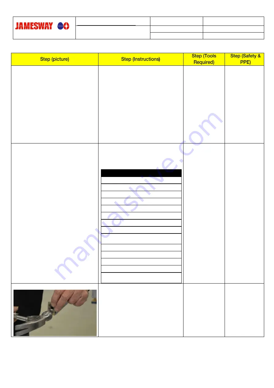
JIC-INSTP2-00004 Step 2 


Insert 2x AB7493 Nut Plate weldment into 
the AB7419 ECU center support assembly. 
 
The nut side should go into the leg. It may 
have to be hammered in place.  
 
Ensure the nut is centered in the leg. 

 
Hammer 


Summary of Contents for Platinum 2.0

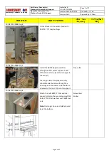
Page 1: ...Step 1 Open the FB6278 pack and inventory to ensure the following components are present Part Description PB5947 4 Pipe ECU Centre Support MB20117 2 Plate Front Support MB20006 1 Support Leg L H MB200...

Page 2: ...AB7419 ECU center support assembly The shorter side from the gap should be on the long side without the shelf of the main support piece Ensure the nut plate is centered in the opening of the JIC INST...

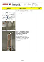
Page 3: ...bushings JIC INSTP2 00004 Step 7 Install the AB7430 pipe assemblies through the ECU center support Cut 4 off the two return pipes the two pipes in the center The longer side of the pipe assembly shou...

Page 4: ...ep 9 Fasten the support leg to the shelf of the frame using P314 bolts PT1195 washers on the support leg side and P6395 lock nuts Screwdriver Socket JIC INSTP2 00004 Step 10 Stand the assembly upright...

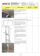
Page 5: ...sing 2x P6200 self drilling screws Note Do not attach the support to the floor at this point Alignment will need to be checked when the front and back ECU supports are installed Drill 2 Phillips drive...

Page 6: ...liquid tight into the hole 11 5 mm drill bit PG7 tap Drill Hot Water Lines JIC INSTP2 00004 Step 15 When the hot and cold water lines are installed the solenoids will be located to the outside on the...

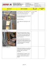
Page 7: ...ter support and are inline down the cabinet JIC INSTP2 00004 Step 18 Silicone around the pipe roof joints both inside and outside the cabinet Leave the support 2x4s in place for at least 24 hours whil...

Page 8: ...ut the PB4590 PVC conduit into two lengths 57 145 mm 19 48 mm JIC INSTP2 00004 Step 22 From the inside screw the PB4841 PVC adaptor into the tapped hole in the centre roof extrusion JIC INSTP2 00004 S...

Page 9: ...ent glue glue the long PVC conduit into the roof adaptor JIC INSTP2 00004 Step 25 Glue the coupling to the bottom of the long pipe and orient in place over the hole through the top plate of the ECU st...

Page 10: ...abinet Wiring the Solenoid Valves Pre 24VDC controls JIC INSTP2 00004 Step 30 From the roof feed the wiring for the solenoid valves along the low voltage trough and down the PVC conduit to the connect...

Page 11: ...d be run through the top liquid tights and the rear valve cables should be run through the bottom JIC INSTP2 00004 Step 34 Ensure that each liquid tight connector is firmly screwed into the electrical...

Page 12: ...duct support shelf on the center ECU support using 4 each of P314 machine screws and P6395 lock nuts JIC INSTP2 00004 Step 39 Insert the intake damper assembly through the holes of the roof and into t...

Page 13: ...C INSTP2 00004 Step 42 Silicone around the assembly and roof joint both inside and outside the cabinet JIC INSTP2 00004 Step 43 The centre support requires the installation of two magnetic catches on...

Page 14: ...n OP100027 Exhaust Dampers procedure JIC INSTP2 00004 Step 47 The intake dampers will be wired once the exhaust dampers are in place Proceed to finishing the cabinet with the add ons exhaust dampers a...

Page 15: ...vision No A Approved By S Ditner Page 15 of 17 JIC INSTP2 00004 Step 50 Drill out the holes in the Pilot duct through the intake duct Mount the duct using PT1234 machine screws PT1195 washers and P611...

Page 16: ...Support Revision Date 04 03 2018 Revised By V Frail Revision No A Approved By S Ditner Page 16 of 17 JIC INSTP2 00004 Step 52 Thread the connection wire out of the top of the duct through the liquid...

Page 17: ...Revised By V Frail Revision No A Approved By S Ditner Page 17 of 17 JIC INSTP2 00004 Step 55 Thread the Pilot egg cable through the liquid tight in the center roof extrusion and tighten fully Leave a...

Reviews: