Pre-installation
Please read all of these instructions before mounting any products or installing any wires and cables.
AM4.6
IMPORTANT.
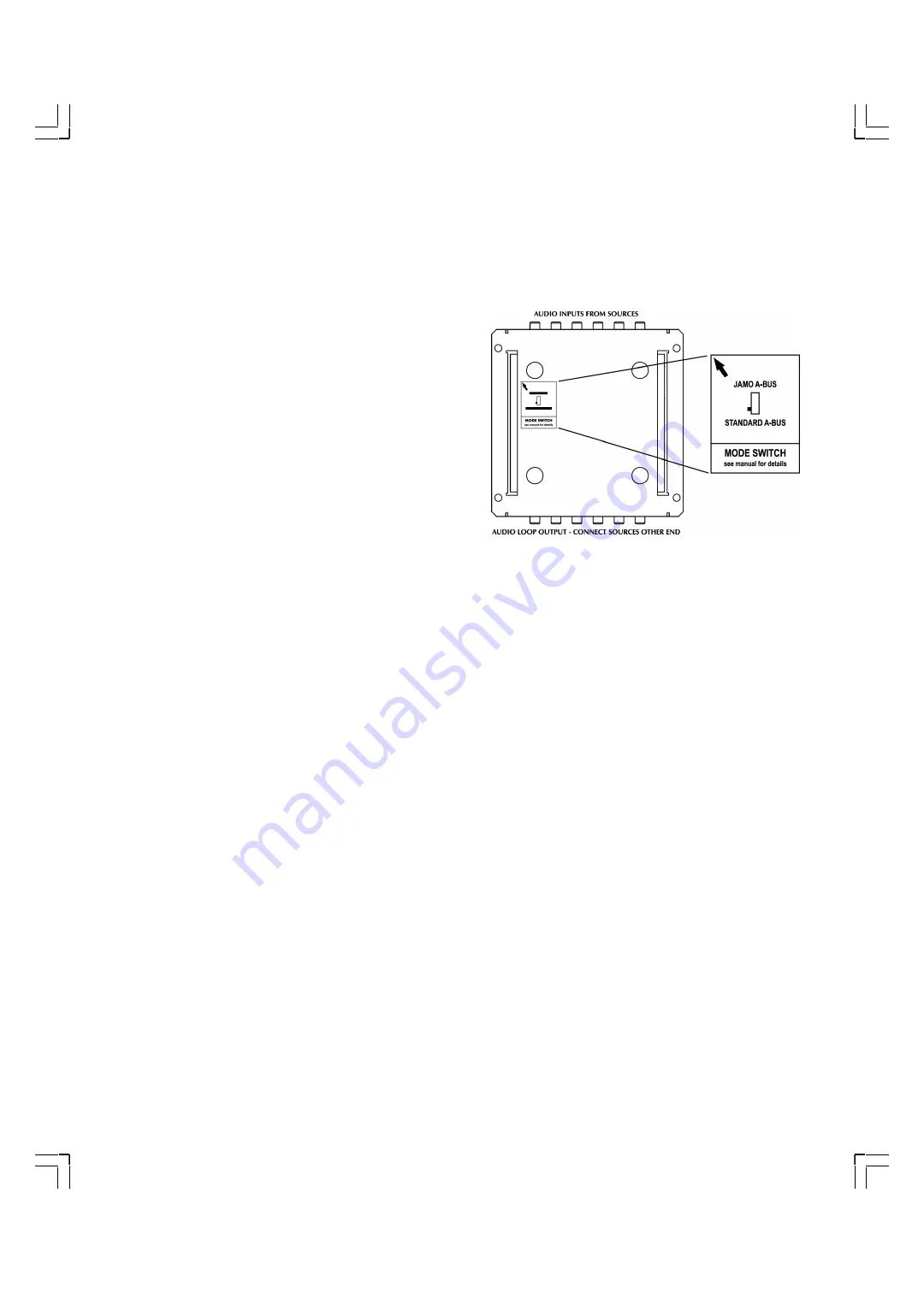
The AM4.6 can be switched between Jamo A-BUS
or standard A-BUS mode. The Jamo A-BUS position is used with
the Jamo KP4.6 keypad and gives extra functions. When used
with other A-BUS keypads it should be set to Standard A-BUS or
they will not work. The switch is located on the rear of the
AM4.6.
The AM4.6 should be mounted on a hard surface. Do not
mount on a carpeted surface as this may limit the airflow
through the unit. It should be located within 10 feet from a
power outlet.
It should not be located close to any product or installation
which produces excessive electrical noise as these could inter-
fere with the AM4.6. These could be dimmer racks etc.
VM4.6
Install the VM4.6 within 15 feet from the AM4.6. The same surface instructions as the AM4.6 should be followed as well as the
consideration of electrical noise sources.
Wiring and Cabling
Install a single-gang 2” or deeper J box or a P ring at each KP4.6 location. If using a J box all knock outs must be removed to
provide ventilation.
Run a CAT5e cable from the AM4.6 to each KP4.6 location.
Run two speaker wires from the KP4.6 location to the speaker locations for that zone.
For video distribution (optional) run RG6 or other coaxial cable from the VM4.6 to the TV/Monitor location. It can be termi-
nated directly to the TV/Monitor or to a suitable wall plate fitted with a co-axial connector.
CAT5e cables should be run through conduits whenever possible, however when not available or practical special care
should be taken not to install the cable close to sharp edges and avoid risk of kinking or trapping. Do not over tighten cable
ties. Similar precaution should be taken to installation of speaker wires.
Make sure and re-check that the color code on the CAT5e cable connections are correct.
KP4.6
The KP4.6 should be located around 55” off the floor and 10-15” from door frames or wall edges, taking into account the loca-
tion of light switches etc. It should not be located where exposed to direct sunlight as this can interfere with the infra-red
sensor.
The KP4.6 should be installed in a single-gang 2” or deeper J box or in a P ring.
The CAT5e cable is connected to the KP4.6 at the color coded 8-way screw terminal on the rear.
Speaker wires are connected to screw terminals on the rear of the KP4.6.
See the manual supplied with the KP4.6 for complete installation instructions.
5
Summary of Contents for AVD4.6
Page 1: ...AVD4 6 Installation Guide...
Page 12: ...www jamo com...


