background image

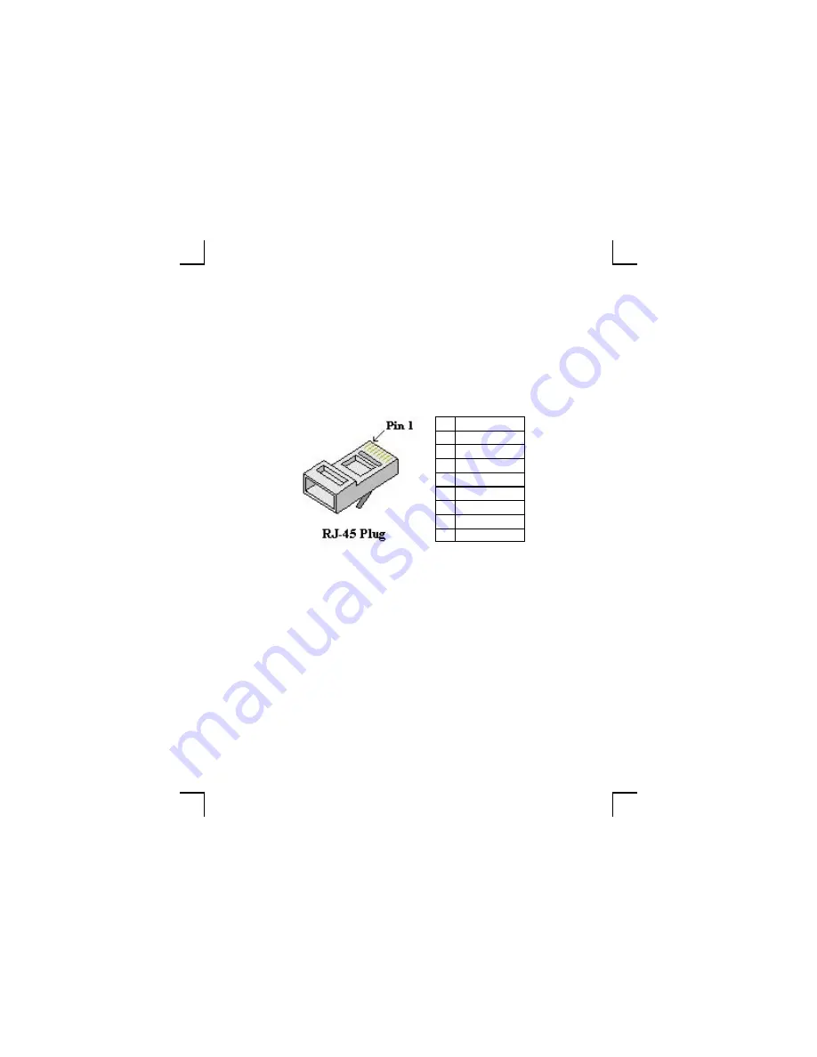
Fig. 2 

The Cat5e should be terminated in the RJ45 plug as per 

T-568A standard. Fig. 2. 

Pin   Color Code 

white/green 

green 

3  white/orange 

blue 

white/blue 

orange 

7  white/brown 

brown 

Pre-installation


Summary of Contents for KP4.6

Page 1: ...KP4 6 Installation User Guide ...

Page 2: ...video to multi ple rooms and locations in your home After it is installed you have access to all your cen trally located audio and video equipment through stylish wall mounted control panels or remote con trols from each location with a control panel in stalled Sound is delivered to in wall or ceiling speakers or conventional speakers if preferred and video is delivered to televisions or monitors ...

Page 3: ...3 Content Important Pre installation Installation Operation Specifications Limited warranty 4 5 7 8 10 11 13 14 15 ...

Page 4: ... is safe with most plasma TV s Do not install the KP4 6 close to dimmer switches as they gener ate noise Do not install the KP4 6 in areas with high humidity or outdoors Do not install the KP4 6 within line of sight to another KP4 6 This could make it difficult to control each zone separately with a remote control Do not install the KP4 6 within line of sight to the source equip ment This could in...

Page 5: ...aker wires connects the KP4 6 to a pair of speakers Speakers from 4 to 8 ohm with a sensitivity of min 88dB should be used All Jamo speakers match these specifications Cat5e Speaker wires Source equipment Jamo AM4 6 or other equipment with A Bus ready socket KP4 6 To speaker locations Fig 1 ...

Page 6: ... Fig 2 The Cat5e should be terminated in the RJ45 plug as per T 568A standard Fig 2 Pin Color Code 1 white green 2 green 3 white orange 4 blue 5 white blue 6 orange 7 white brown 8 brown Pre installation ...

Page 7: ...tched between normal A BUS or enhanced Jamo A BUS mode The A BUS position is for use with other A BUS equipment The Jamo position is for use with Jamo AM4 6 and gives extra functions The switch MUST be set in the correct position or the KP4 6 will not work ...

Page 8: ...8 Installation Screened audio cable KP4 6 Fig 4 Subwoofer The KP4 6 has a preamp output for external equipment powered subwoofer or amplifier Use a screened audio cable for connection ...

Page 9: ...nect the Cat5e cable to the screw terminals with a phillips screwdriver Fig 4 Next connect the speaker wires to the screw terminals with a phillips screwdriver Fig 4 Make sure to follow the color coding for both Cat5e ca ble and speaker wires ...

Page 10: ...nstallation Fig 6 Screw locations Install the KP4 6 in a single gang 2 or deeper J box or in a P ring with the 2 supplied screws Fig 5 Install any decora style faceplate on to the KP4 6 module not included ...

Page 11: ...r Treble three times for Balance and four times for Fader If still held it will return to Bass and cycle through again Start to adjust the desired func tion within 2 sec or the system goes back to volume ad justment LED green When adjusting Bass Treble Balance and Fader the LED blinks orange The led blinks red when reaching the top or bottom end and blinks green at the mid point no ad justment to ...

Page 12: ...12 Operation Standby Down IR window Select Up Status LED Sound ...

Page 13: ...d to indicate signal received Select Short push to change source Sound Long push 4 sec to enter Sound Adjustment functions Up Adjusts volume bass and treble up Adjusts balance to right and fader to main speakers LED Keypad on Solid green Keypad off Off Keypad in mute Blinks green Adjusting volume or sound Blinks or ange End points on volume or sound Blinks red Change source Blinks twice for each p...

Page 14: ... range 80dB 32 steps Bass control range 16dB 2dB steps Treble control range 16dB 2dB steps Balance control range 40dB 9 steps each way Fader control range 40dB 9 steps each way Preamp out Variable level follows volume setting IR pass through 34 40kHz and 54 58kHz modulation freq Speaker impedance 4 8 ohm Power requirement 24 V DC 1 A max ...

Page 15: ... misuse normal wear and tear mis maintenance voltage variation stroke of light ning and other force major events Defects arising from incorrect installation or operation Defects arising from modification repair attempt of repair by a non authorized service center or person Defects arising form the use of non original spare parts Defects on products with altered or lacking serial number Other defec...

Page 16: ...www jamo com ...

Reviews: