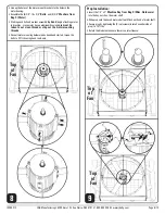
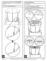
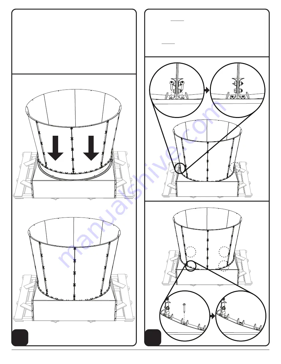
background image

Cone Installation:

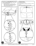
• Using (2) people lift the cone assembly onto the housing assembly.

— With J&D logoed cone sections facing the sides (not the top and 


    bottom) line up the edge of one of the cone pieces to the center 


    line of the housing. 
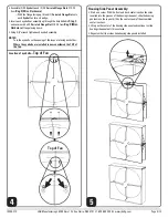
— Make sure the raised part of the rubber gasket is inside the 


    cone assembly and not underneath it or crushed anywhere.

NOTE: 

During the following process of securing the cone to the housing, 

             recheck the rubber gasket for proper placement and make adjust-

             ments as needed

IS295-21C 

J&D Manufacturing • 6200 Hwy 12 • Eau Claire, WI 54701 • 1-800-998-2398 • www.jdmfg.com 

Page 9/13

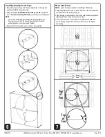
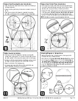
• Align the top and bottom of the cone at the areas of the damper door    

   bracket (see 

Step 10

) and secure using the included 

#3 Phillips Bit 

   from Bag 1 (Tools)

 and

 (4) #14-10 x 2” 

Screws from Bag 5 

   (Part 1) 

as shown below

• Align the cone at the areas of the 4 damper door striker plates placed 

   in (see 

Step 12

) and secure using the included 

#3 Phillips Bit from 

   Bag 1 (Tools)

 and

 (4) #14-10 x 2” 

Screws from Bag 5 (Part 1) 

   as shown below

16

17

Summary of Contents for MAGNUM 58"

Page 1: ...ly installed or subject to negligence All warranties must be approved through our warranty department The original purchaser must present a copy of the invoice for the defective product Please read over ALL instructions carefully before you begin If you have any questions please call your local dealer or contact J D Manufacturing at 1 800 998 2398 RECOMMENDED TOOLS SUPPLIES FOR INSTALLATION AND AS...

Page 2: ...uard 8 5 16 18 x 1 Bolts 8 5 16 18 Serrated Flange Nuts Bag 7 Mounting Screws 4 12 11 x 3 Screws Use 3 Phillips Bit from Bag 1 Bag 8 Motor Guard 10 12 11 x 5 8 Screws Use 3 Phillips Bit from Bag 1 Bag 5 Cone Bag 5 Part 1 50 14 10 x 2 Screws Use 3 Phillips Bit from Bag 1 Bag 5 Part 2 50 5 16 18 x 7 8 Bolts Bag 5 Part 3 50 5 16 18 Serrated Flange Nuts Bag 4 Damper Doors 5 4 40 x 3 4 Screw 5 4 40 Loc...

Page 3: ...venturi sections Tighten only the bolts and nuts securing venturi sections Holding the motor brackets up so the back side is flush to the outside of the venturi sections tighten the bolts and nuts securing motor mounts and venturi sections 2 Eye Bolt Installation Stand the housing assembly up Locate the dimple marks on the exterior of the venturi next to the motor brackets With a 13 64 drill bit d...

Page 4: ...g each other Where the eyebolts are installed is now considered the TOP of the fan 4 Housing Side Panel Assembly Start on a corner With the front and back venturi section channels inserted into the grooves of the housing side panel slide the housing panel across the top until it hits the center seam of the assembled venturi sections Lift up on the center of the housing side panel and continue to s...

Page 5: ...til all four housing corner caps have been installed 6 IS295 21C J D Manufacturing 6200 Hwy 12 Eau Claire WI 54701 1 800 998 2398 www jdmfg com Page 5 13 Top of Fan Top of Fan Motor Installation NOTE 2 person lift is recommended for handling of 105lb motor Using the pallet the fan came on place the motor in the center between the pallet slats with the shaft facing up Place housing curved side down...

Page 6: ...otor mounting hardware has been hand started torque the bolts to 23 ft lbs using hand tools only 8 Prop Installation Insert the 1 4 x 2 Machine Key from Bag 9 Misc Hardware into the key notch on the motor shaft Slide prop onto the keyed motor shaft until flush with end of motor shaft Secure prop by tightening the 2 set screws located on underside of prop to 10 ft lbs Rotate the blade to make sure ...

Page 7: ...uri under the just placed rubber gasket locate the 4 striker plate grooves nearest the center of the fan venturi do not use the ones nearest the top or the bottom of the fan Carefully lift off the rubber gasket over the striker plate groove and insert 1 SS Damper Door Striker Plates from Bag 9 Misc Hardware at each location angle the striker plate so the angle matches the fan housing To secure the...

Page 8: ...ieces are assembled Using a 1 2 socket with impact driver and wrench tighten the cone pieces together 15 Installing Damper Door Insert damper door rod fully into the top part of the damper door mounting bracket then slide damper door down so that the damper door rod end rests against the stop on the damper door mounting bracket as shown below Repeat for second damper door 14 IS295 21C J D Manufact...

Page 9: ...the housing recheck the rubber gasket for proper placement and make adjust ments as needed IS295 21C J D Manufacturing 6200 Hwy 12 Eau Claire WI 54701 1 800 998 2398 www jdmfg com Page 9 13 Align the top and bottom of the cone at the areas of the damper door bracket see Step 10 and secure using the included 3 Phillips Bit from Bag 1 Tools and 4 14 10 x 2 Screws from Bag 5 Part 1 as shown below Ali...

Page 10: ...are from Bag 9 Misc Hardware insert hub bolt post between the two front guard pieces center and secure with washer and nut 19 Finish securing the cone to the housing using the included 3 Phillips Bit from Bag 1 Tools and 14 10 x 2 Screws from Bag 5 Part 1 Cone is fully secure once each section of cone is secured with a total of 6 14 10 x 2 Screws from Bag 5 Part 1 18 IS295 21C J D Manufacturing 62...

Page 11: ...g tension Continue until the correct spring tension is found 20 Top of Fan Magnum Installation From the exterior of the building insert fan into opening Using the included 3 Phillips Bit from Bag 1 Tools and 4 12 11 x 3 Screws from Bag 7 Mounting Screws secure fan in opening as shown below NOTE For steel frame applications we recommend the equivalent size hex head self drilling TEKS screw not incl...

Page 12: ...F Connect 10V OUT wire to 10V IN wire for no speed control full speed Use four conductor 26AWG or heavier shielded dual twisted pair signal wire with drain wire from J D control to Permanent Magnet fan DISCONNECT POWER BEFORE INSTALLING OR SERVICING ALL ELECTRICAL WORK SHOULD BE COMPLETED BY QUALIFIED PERSONNEL AND MEET NATIONAL NEC REGIONAL AND LOCAL ELECTRIC CODES Control Power General Wiring In...

Page 13: ...ripe Maintenance Instructions Disconnect power before cleaning or maintaining your fan in order to prevent serious injury or death Service and repair of fan should only be completed by a qualified technician For maximum efficiency and fan life keep the following free from dirt and dust blades damper doors motor and guard The totally enclosed air over motor has sealed ball bearings and does not req...

Reviews: