


Slide cone onto venturi so that venturi and cone overlap by approximately
2”. Use marks made in step 3 as your guide.
5
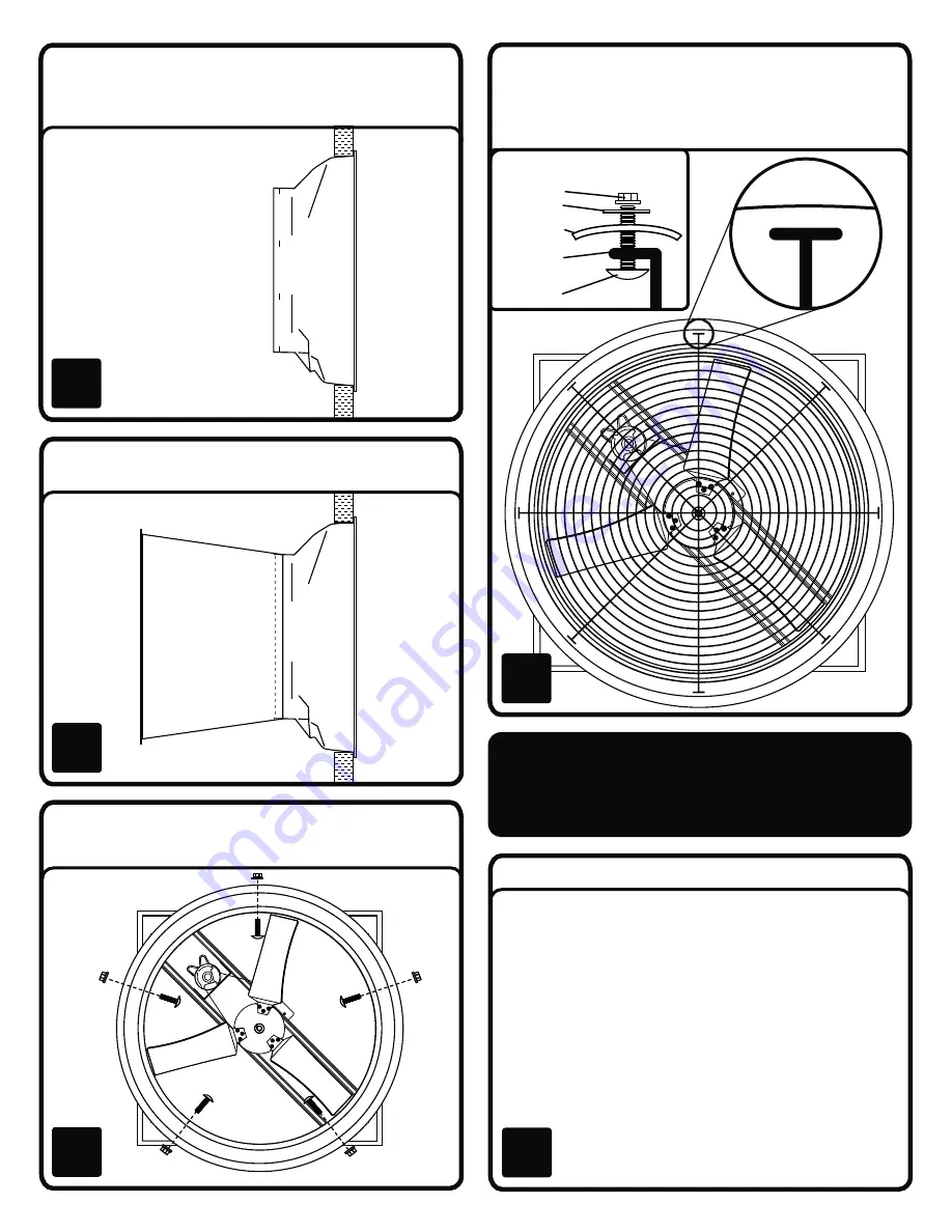
Insert guard into cone. Using the predrilled holes in the end of the cone,
secure the guard to the cone using (8) 5/16” Hex Bolts, (8) 5/16” Flat
Washers, and (8) 5/16” Nylock Flange Nuts. Review the Assembly Side
View illustration for proper installation. Do not tighten until all have been
assembled.
7
From the inside of your structure, rotate the fan housing until the motor is
located above and to the right of the shaft, as shown in the illustration on
the front page. Insert fan housing into the finished opening and secure all 4
sides to structure using suitable fasteners and washers (not included).
4
Interior
of structure
Exterior
of structure
Using the 5 predrilled holes in the cone, drill matching holes in venturi and
secure with (5) 5/16” Phillips Truss Bolts and (5) 5/16” Nylock Nuts. Insert
bolt from the interior of the cone and secure with nut on exterior.
6
Assembly Side View
Connecting power to the unit.
• Install manual disconnect switch inside
building adjacent to fan.
• Route wire to motor with drip loop and
secure. Drip loop will drain accumulated
moisture away from the motor.
• Configure internal wires to match supply
voltage and wire according to motor
nameplate. Test to verify correct rotation.
• Shut off manual disconnect for remainder
of install. Only permit power to unit when
shutter and guard is fully installed to
prevent injury.
8
ALL ELECTRICAL WORK SHOULD BE
COMPLETED BY QUALIFIED PERSONNEL AND
MEET NATIONAL, REGIONAL AND LOCAL CODES
Nut
Cone
Guard
Mounting
Foot
Washer
Bolt


