background image


CELLAR PLUS CELLAR COOLER 

 RANGE 


ISSUE: 01.07.2020 


CELLAR COOLER


RANGE


TECHNICAL MANUAL 


Summary of Contents for Cellar Plus 70-S1

Page 1: ...CELLAR PLUS CELLAR COOLER RANGE ISSUE 01 07 2020 CELLAR COOLER RANGE TECHNICAL MANUAL...

Page 2: ...ctrical 16 Commissioning General 17 Pre startup checks running the unit compressor operation 18 Vacuum Operation 19 Safety pressure switch setting 19 High pressure safety 19 Low pressure safety 19 Com...

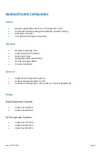
Page 3: ...r Housed condensing units Copeland scroll compressor Basic control box Adjustable LP HP switch fitted Drier sight glass fitted Acoustic insulation General Single Twin Evaporator systems Cellar tempera...

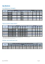
Page 4: ...ystem COP 3350 1 2 5 8 1 2 3 4 1 2 3 4 7 94 Nominal Capacity 1 kW 1x JCC2 80E 2x JCC2 40E 2x JCC2 60E 1x JCC2 80E 34 36 34 2765 2x 2560 1 2 5 8 4250 3350 36 41 1 2 3 4 2x 2680 4070 4070 2x 2270 10 10...

Page 5: ...2 0 12 2 25 BSCU 30 M3 400 3 50 10 3 40 0 5 1 16 BSCU 35 M1 230 1 50 25 0 97 0 14 0 32 BSCU 35 M3 400 3 50 9 0 46 0 5 7 20 BSCU 30 M1 230 1 50 21 5 82 0 13 3 25 BSCU 30 M3 400 3 50 10 3 40 0 5 4 16 BS...

Page 6: ...ds which may cause severe injury or death Disconnect and shut off power before installation or service of the equipment Refrigerant release into the atmosphere is illegal Proper evacuation recovery ha...

Page 7: ...ized solenoid valve needs to be installed in the liquid line just before the TEV on single evaporator systems and just before the T piece in the main liquid line on Twin Systems as shown on page 8 The...

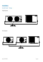
Page 8: ...Issue 01 07 2020 Page 8 Installation Quick Guide Piping Single System Twin System...

Page 9: ...ction Twin The JCC evaporators come pre fitted with an electronic controller as standard For the Twin Systems one of the evaporators needs to be designated as the Lead Unit with the other being the La...

Page 10: ...n and distribute plenty of air thus lowering the condensing temperature To optimize the unit running conditions the condenser coil must be cleaned at regular intervals The evaporators can be mounted d...

Page 11: ...Installation Installation clearances The installation location should allow sufficient space for air flow and maintenance around the units Outdoor Indoor 500mm 500mm 1500mm to any obstruction Minimum...

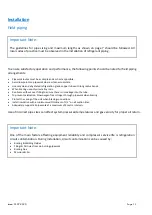
Page 12: ...ng of the unit when brazing connections Install insulation with a minimum wall thickness of 1 2 on all suction lines Adequately support all pipe work at a maximum of 2 metre intervals Use of incorrect...

Page 13: ...he area surrounding the system is safe inform relevant personnel and fit warning signs indicating high pressure testing Also use correct PPE as required Listen for any possible leaks and check all joi...

Page 14: ...isture is suspected Once the system is isolated and the vacuum pump is switched off any rise in pressure indicates that either there may be a leak in the system or moisture is still present In this ca...

Page 15: ...in from the indoor unit is 20mm or 3 4 This can be either copper or plastic Flexible hose is not recommended as it can easily kink causing a blockage and water to back up in the unit Important Note Th...

Page 16: ...n access to the electrical box on the outdoor unit remove the screws of the panel located on the right hand side of the unit and remove the panel The electrical box is located behind the panel Importa...

Page 17: ...period is adequate to clear any frost build up on the evaporator coil Carry out final leak test and ensure all covers are fitted and securing screws are tightened Log all information along with syste...

Page 18: ...responsible person is provided with basic operating instructions and where electrical isolators are situated in case of emergency Compressor operation Scroll compressor motors are designed to run onl...

Page 19: ...e high pressure switch can be set to lower values depending on the ambient conditions Low pressure safety The low pressure safety switch protects the compressor against deep vacuum operation a potenti...

Page 20: ...icated and factory sealed so no maintenance is necessary 3 Condenser Evaporator Coils Clean and inspect at regular intervals Check and remove the dirt and debris between the fins using a soft brush an...

Page 21: ...e installer or local authority for more information Batteries must be removed from the controller and disposed of separately in accordance with relevant local and national legislation 8 Component repl...

Page 22: ...leak testing requirements are as follows OLD LEGISLATION NEW LEGISLATION LEAK CHECKING FREQUENCY 3 30 kgs 5 50 TCO Eq Every 12 months but can be increased to 24 months if fitted with a fixed leak det...

Page 23: ...Issue 01 07 2020 Page 23 Drawings Dimensional drawings Indoor Units 40E Dimensional drawings Indoor Units 50E 60E...

Page 24: ...Issue 01 07 2020 Page 24 Drawings Dimensional drawings Indoor Unit 80E...

Page 25: ...Issue 01 07 2020 Page 25 Drawings Dimensional drawings Outdoor Units BSCU 30 M1 M3 BSCU 35 M1 M3...

Page 26: ...Issue 01 07 2020 Page 26 Drawings Dimensional drawings Outdoor Units BSCU 40 M1 M3...

Page 27: ...Issue 01 07 2020 Page 27 Drawings Electrical wiring diagrams Indoor Indoor JCC2 40E 50E 60E JCC2 80E Indoor Lead Lag Twin...

Page 28: ...Issue 01 07 2020 Page 28 Drawings Electrical wiring diagrams Outdoor BSCU 30 M1 BSCU 35 M1 BSCU 40 M1...

Page 29: ...Issue 01 07 2020 Page 29 Drawings Electrical wiring diagrams Outdoor BSCU 30 M3 BSCU 35 M3 BSCU 40 M3...

Page 30: ...the programming mode by pressing the SET and the buttons together for more than 3 seconds C or F LED starts blinking The first parameter Hy is displayed Press the SET button to display the parameter v...

Page 31: ...alarm condition and its signalling With iF do it represents the delay to activate the door open alarm 0 99 minutes 5 5 LS Minimum Set Point 55 C 67 F 55 C 55 F 4 C US Maximum Set Point 99 C 210 F 99 C...

Page 32: ...after setting Low pressure side Range Turning the range adjusting screw 2 clockwise will decrease the cut in pressure setting Turning the range adjusting screw anti clockwise will increase the cut in...

Page 33: ...Issue 01 07 2020 Page 33 Certification...

Page 34: ...Issue 01 07 2020 Page 34 THIS PAGE IS LEFT BLANK INTENTIONALLY...

Page 35: ...J E Hall Limited Hansard Gate West Meadows Derby DE21 6JN England Tel 44 0 1332 253400 Fax 44 0 1332 371061 Email helpline jehall co uk www jehall com Issue 01 07 2020...

Reviews: