background image

14

1.0   Operations

8. 

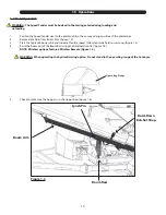
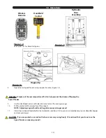
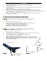
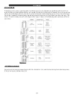
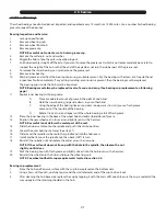
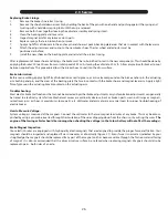
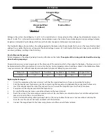
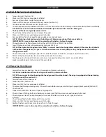
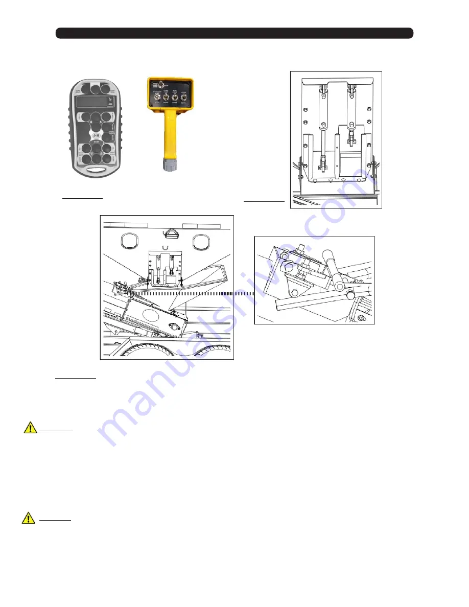
Open door on Speed Tender using supplied remote. (Figure 1.4).


   WARNING:  Empty-out the rear compartment first to help prevent the chance of flipping the  


  Speed Tender.

9. 

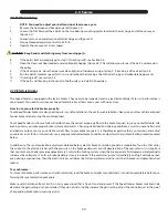
Use the Handheld Control or Wireless Remote to start the conveyor/auger.

10. 

Fill the planter/drill to desired level then repeat.


NOTE:  Adjusting engine throttle will regulate conveyor/auger speed.

11. 

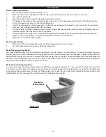
Close door on Speed Tender before the last planter seed box is full so you can completely empty-out collapsible hopper  


and conveyor/auger.

   CAUTION:  If you are parked on an incline the boom arm may swing freely. (It is advised that you do not use the  
 

Speed Tender on uneven ground).

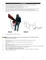
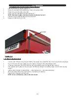
Figure 1.6

Figure 1.4

See Section 4.1 for Remote Options

Figure 1.5

Wireless 

Remote

Handheld

Control

Hopper Up

Hydraulic

Door

Assembly

Summary of Contents for 510-ST

Page 1: ...OPERATORS MANUAL J M Mfg Co Inc 284 Railroad Street P O Box 547 Fort Recovery OH 45846 Ph 419 375 2376 Fax 419 375 2708 www jm inc com 510 ST Rev 2 23 2016 Speed Tender...

Page 2: ...vice 34 36 Hydraulics 37 41 Wiring 42 55 Repair Parts 43 Ladder Parts 44 Scale Parts 45 Chassis Parts 46 A Frame Goosneck Parts 47 Boom Arm Parts 48 49 Conveyor Parts 50 Swing Cylinder 50 Door Parts 5...

Page 3: ...3...

Page 4: ...cation or repair ii accident abuse or improper use iii improper or insufficient maintenance or iv normal wear or tear This warranty does not cover products that are previously owned and extends solely...

Page 5: ...in 49 front to rear swing Two 2 7 000 lb Torsion Flex 11 HP Honda Motor Conveyor Axles w Electric Brakes w Electric Start Two 2 50 Unit Boxes 3 800 lbs 580 lbs 16 Spout Height 4 Minutes per Box 42 w o...

Page 6: ...hat will help you achieve years of dependable performance and help maintain safe operating conditions If this machine is used by an employee or is loaned or rented make certain that the operator s pri...

Page 7: ...perating close to ditches fences or on hillsides Use care when moving or operating Speed Tender near electric lines as serious injury or death can result from contact Never adjust service clean or lub...

Page 8: ...wering Decal JM0014992 7 Warning Lug Nuts Tight Decal 8 J M Oval Tru Trak Decal 9 Danger Flowing Grain Traps ST Decal 10 Warning Shut off Power Before Service 11 Speed Tender Decal JM0015002 12 J M Ov...

Page 9: ...9 Decals 4 11 13 7 12 14 9 10 11 16 15 17...

Page 10: ...tire pressure and wheel torque located in service manual section 1 3 Connecting Speed Tender to the Towing Vehicle WARNING Do not stand between the Speed Tender and tow vehicle when hooking up NOTE Th...

Page 11: ...lighting and marking requirements WARNING Travel at a safe speed that allows you to maintain complete control of towing vehicle and Speed Tender at all times 1 5 Hydraulic Power Unit Operation WARNIN...

Page 12: ...sition Figure 1 2 3 Slide Choke Lever to the ON position Figure 1 2 4 Turn the key to the start position Once engine starts release key Figure 1 2 5 After starting allow the engine to warm up Slide ch...

Page 13: ...rt the hydraulic power unit and increase throttle speed Allow hydraulic fluid to warm up Figure 1 2 4 Raise the boom out of the Boom Rest using the handheld control Figure 1 4 NOTE Wireless options fe...

Page 14: ...el then repeat NOTE Adjusting engine throttle will regulate conveyor auger speed 11 Close door on Speed Tender before the last planter seed box is full so you can completely empty out collapsible hopp...

Page 15: ...vehicle during loading and unloading 1 Remove lynch pin from Boom Arm Figure 1 3 2 Start the hydraulic power unit and increase throttle speed Allow hydraulic fluid to warm up NOTE Make sure collapsibl...

Page 16: ...tight enough that the conveyor will not move during transport 23 Make sure the collapsible hopper is in the up position for storage Figure 1 6 NOTE This will help the water drain out of the hopper 24...

Page 17: ...an incline the boom arm may swing freely It is advised that you do not use Speed Tender on uneven ground 13 With the boom arm at a 45 Deg angle swing the conveyor back into the resting position on th...

Page 18: ...ows Hello then the current weight value is displayed 2 Press G N to access the gross mode Live scale weight is displayed in the G N weighing mode 3 In the gross mode press the ZERO CLEAR key to zero t...

Page 19: ...ing Figure 2 1 NOTE Over lubrication of these bearings will result in premature failure NOTE The conveyor has four bearings that need grease two at each end The auger is equipped with one bearing at h...

Page 20: ...not exceed maximum recommended tire pressure 80 psi is the cold rating on the tire that is standard for the Speed Tender J M also recommends to rotate your tires front to back not side to side every 1...

Page 21: ...ther hand C Using the edge of the bearing like an ice cream scoop work it in until you see fresh grease come out of the top side of the bearing D Rotate 1 8 of a turn and repeat until the whole bearin...

Page 22: ...servoir and refill as needed 4 Pressurize system again to reverse the motion of step 2 Maintain pressure on system for at least 5 sec after cylinder rods stop moving Check that cylinders have fully ex...

Page 23: ...g in the center of the pulley NOTE Do not loosen the Adjustment bolt 5 Tighten all bolts on bearing mounting plate and adjustment bolts jam nuts 6 Repeat at discharge end 7 When belt is running in cen...

Page 24: ...the combined load Your Speed Tender and tow vehicle will seldom have the correct amperage flow to the brake magnets to give you comfortable safe braking unless you make proper brake system adjustment...

Page 25: ...to adjust brakes 1 After the first 200 miles of operating when the brake shoes and drums have seated 2 At 3 000 mile intervals or once a year whichever comes first Brake Cleaning and Inspection Your S...

Page 26: ...g plate that are in contact with the brake shoes and magnet lever arm Apply a light film of grease on the actuating block mounted on the actuating arm Troubleshooting Most electric brake malfunctions...

Page 27: ...ed and the amp meter put in series into the line System amperage draw should be as noted in the table below Make sure your ammeter has sufficient capacity and note polarity to prevent damaging your am...

Page 28: ...ic oil level 4 Inspect for oil leaks and repair as appropriate 5 Check all hoses fittings bolts and hardware to make sure that they are secure and properly tightened 6 Check engine oil level See Engin...

Page 29: ...draulic Oil should be changed more often 15 Check motor oil level See Engine operator s manual for details on oil levels oil types and service intervals 16 Retract all hydraulic cylinders to prevent t...

Page 30: ...rings in brakes Locking brakes a Replace any weak or broken springs in brakes b Replace any excessively worn or contaminated linings Grabbing brakes a Replace any excessively worn or contaminated lini...

Page 31: ...up or down Hydraulic pump is not producing sufficient pressure or volume to hydraulic cylinder a Check for pinched or leaking hydraulic lines b Allow hydraulic oil to warm up c Increase engine R P M...

Page 32: ...lloy Steel 1 4 20 6 9 10 12 5 13 14 5 16 18 12 17 19 24 25 29 3 8 16 20 30 33 43 44 47 7 16 14 32 47 54 69 71 78 1 2 13 47 69 78 106 110 119 9 16 12 69 103 114 150 154 169 5 8 11 96 145 154 209 215 23...

Page 33: ...33...

Page 34: ...17 20 21 22 23 24 25 26 27 28 29 30 30 30 30 4 4 Power Unit Motor Rear Door Front Door Swing Cyl Boom Cyl Aluminum Valve Block Top Ports Bottom Ports B o o m C y l S w i n g C y l F r o n t D o o r R...

Page 35: ...2 male JIC X 1 2 male NPT straight JM0015201 16 1 2 male JIC X 3 4 male NPT 90 degree elbow JM0033775 17 Hydraulic Power Unit JM0003027 18 5 Function Aluminum Valve Block JM0029973 19 WR series Hydra...

Page 36: ...torque There is a spring poppit and ball bearing at the bottom of each coil Top Coil operates bottom port Bottom Coil operates top port When changing cartridge make sure all functions are at rest The...

Page 37: ...N C HandheldController Starts Stops Motor Raises Lowers Conveyer Opens Closes Tank Doors Hydraulic Conveyer Swing JM0014991 JM0031012 Stationary Control Raises Lowers Conveyer Opens Closes Tank Doors...

Page 38: ...Auto Dispense button again to repeat the process This can be done during the conveyor cleanout stage Setting the desired Auto Dispense Weight Press Scroll 2 to enter Auto Dispense menu Hold Tare 3 til...

Page 39: ...Red Marker Light To Scale Box optional To Left Brake Light To License Plate Light To Rear Top Harness To Rear Right Round Red Marker Light To Right Brake Light To A Frame or Goosneck Harness 419 475...

Page 40: ...50 Light Blue Dark Blue To Main Harness Tail Lights Brown Left Turn Brake Yellow 12V Battery Red Right Turn Brake Green Ground White Electric Brakes Blue 7 Way Trailer Connection JM0019962 A Frame JM0...

Page 41: ...Black White 2 2 Onboard Controller Flood Light Switch Harness JM0034135 170 378 C A D B To Tank Flood Light To Auger Conveyor Flood Light Black Black White White Flood Light Harness JM0019965 Black Bl...

Page 42: ...Description Page 5 1 Ladder Parts 41 5 2 Scale Parts 42 5 3 Chassis Parts 43 5 4 A Frame Parts 44 5 5 Boom Arm Parts 45 5 6 Conveyor 46 47 5 7 Swing Cylinder Parts 48 5 8 Hydraulic Door Parts 48 5 9...

Page 43: ...Z Centerlock Hex Nut JM0001512 4 1 2 x 3 8 Shoulder Bolt JM0009998 5 Ladder Linkage 510 JM0031279 6 Ladder Brace 510 JM0026744 7 8 Rung Ladder Assembly 510 JM0031154 8 3 8 16 x 1 Gr5 Z SF Hex Bolt JM0...

Page 44: ...ndle for Scale Box JM0001911 11 Scale Box Dooe Weldment JM0029943 12 Scale Box Assembly Items 5 11 JM0029945 t Description Part No 1 3 8 16 x 3 1 2 Gr5 Z Hex Bolt JM0001986 2 1 2 13 X 1 3 4 Gr5 Z Hex...

Page 45: ...215 75R17 5 Spare Tire Wheel Dual JM0026074 4 5 8 11 x 2 Gr8 Z Hex Bolt JM0001771 5 Wiring Hanger Tab Seed Tender Chassis JM0002346 6 5 8 11 Gr2 Z Centerlock Hex Nut JM0002146 7 1 8 x 6 1 2 Gr5 Z Hex...

Page 46: ...M0002481 4 Jack Stand w Lynch Pin JM0001480 5 1 4 x 3 4 Self Tapping Screw JM0001570 6 Break Away Switch JM0001843 7 2 5 16 Ball Coupler 21 000 Lbs JM0001893 8 1 4 x 1 3 4 Lynch Pin JM0001478 9 Lunett...

Page 47: ...onze Bushing JM0002248 5 1 3 4 x 2 x 1 Bronze Bushing JM0002244 6 Vertical Boom Pivot JM0002241 7 1 8 x 5 Gr8 Pn Hex Bolt JM0001774 8 1 8 Z Gr5 Hex Jam Nut JM0001705 9 4 1 2 x 3 3 4 Hydraulic Cylinder...

Page 48: ...ttom Brush JM0029585 14 Drivel Roller For V Guide Belt JM0021425 15 5 8 11 x 7 1 2 Gr5 Z Hex Bolt JM0001631 16 5 8 11 Gr5 Z Hex Nut JM0001522 17 1 4 20 x 3 4 Gr5 Z SF Hex Bolt JM0001642 18 1 4 20 Gr5...

Page 49: ...M0009998 10 1 4 20 Gr5 Z SF Hex Nut JM0001630 11 Clamp Bar Conveyor Skirt JM0002767 12 1 4 20 x 3 4 Gr5 Z SF Hex Bolt JM0001642 13 Conveyor Hopper Brush Mount JM0027027 14 Tube Conveyor Roll V Guide I...

Page 50: ...tings JM0002261 5 7 Swing Cylinder Parts t Description Part No 1 3 8 16 x 1 Gr5 Z SF Hex Bolt JM0002092 2 3 8 16 Gr5 Z Centerlock Hex Nut JM0001512 3 Hydraulic Door Frame JM0002872 4 3 8 16 Gr5 Z SF H...

Page 51: ...7 7 1 2 13 x 2 Gr8 Z Hex Bolt JM0001620 8 1 2 USS Flat Washer JM0003082 9 Speed Tender Honda GX340 Engine JM0001749 t Description Part No 10 Hydraulic Power Unit JM0003027 11 1 4 20 x 5 1 2 Gr5 Z Hex...

Page 52: ...JM0002903 9 Tarp Hanger Hook JM0002967 10 Rubber Flapper JM0002551 11 3 8 16 x 1 Gr5 Z SF Hex Bolt JM0002092 12 1 2 13 X 1 Gr5 Z Hex Bolt JM0010225 13 1 2 13 Gr5 Z Centerlock Hex Nut JM0001511 14 3 8...

Page 53: ...mbly RH JM0042049 5 16k Drum JM0042046 6 16k Hub 10 on 8 75 JM0042045 7 16k Small Race JM0042015 8 16k Small Bearing JM0042016 9 Spindle Washer 3 OD JM0042050 10 16k Spindle Nut JM0042055 11 16k Cotte...

Page 54: ...Light JM0001908 6 Fender Weldment JM0027229 7 510 Mud Flap JM0036332 8 Rear Fender Step Drivers Side JM0026846 9 Red Round Light JM0001905 10 Red Oval Brake Light JM0001903 11 1 4 20 x 3 4 Gr5 Z SF H...

Page 55: ...55...

Page 56: ...ith Mounting Hardware mounted to inside leg of tank ST235 16TW 6 36 Long Flexible Hose for End of Telescoping Spout ST375FH 36 7 Vinyl Sock for End of Telescoping Spout ST375SK See Section 4 1 Deluxe...

Page 57: ...57 5 0 Parts Includes 6 Dia Clamp with M10 X 1 1 2 L Bolt 5 6 7 8 9...

Page 58: ...llow enough clearance to slide the weigh bars into the Shell Leg Weldment Spools Figure 6 2 5 Slide Weigh Bars into the Shell Leg Weldment Spools and lower the Shell Leg Weldment down so the Weigh Bar...

Page 59: ...Insert the four wires form the weigh bars into the back of the scale indicator box Insert weight bar wires through each grommet 17 Remove the Back Plate from the 640XL Display Interface Figure 6 6 Sa...

Page 60: ...60 6 0 Aftermarket Installation Instructions Weigh Bar Plugins Print Plugin Optional Power Cord Plugin Figure 6 7 Figure 6 6 Back Plate NOTES Wireless Receiver Plugin...

Page 61: ...6 PVC JM0025294 18 Auger JM0029765 12 275ST Pipe Auger Kit JM0031257 2 x 44 PVC JM0030522 46 Auger JM0031254 12 375ST Pipe Auger Kit JM0031256 2 x 55 PVC JM0030521 57 Auger JM0031253 13 Screw Clamp Fo...

Reviews: