background image

Dimmer Operation


11 

 Revision 2.0c – 30 August 2013 

HPC User Manual


5.1.2 Cap Function 

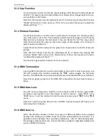
The Cap function is used to scale the output voltage of all channels from the maximum 

of 240V. This may be used to extend lamp life or allows other voltage loads to be run, 

such as 230V or 120V lamps.   
Note that the Cap level may be individually set for a channel by selecting that channels 

“Mode” button when in the cap menu. If this is the case when the menu is entered the 

display will show 

---

“.  


5.1.3 Preheat Function 

The Preheat function is used to inject a small amount of power into the lamps when 

the control level is set to zero. This provides a small amount of energy to heat the lamp 

filament and so minimise thermal shock if  they are flashed to full. This may extend 

lamp life and reduce the surge on the mains supply at the expense of an increase in 

system power consumption. 
Adjust the level until the lamps start to glow, then slowly reduce it until the lamps just 

go dark. 
Note that the Preheat level may be individually set for a channel by selecting that 

channels “Mode” button when in the Preheat menu. If this is the case when the menu 

is entered the display will show

 “

---

“.  

This function is ignored for channels set On or to Switch. 


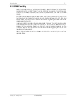
5.1.4 DMX Termination 

Any long DMX-512 data line must be terminated at the end for correct operation, and 

the HPC provides this function. Selecting the

  “

End

  option toggles the terminate 

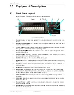
function. The TERM LED on the front panel indicates when the DMX-512 is terminated. 
Note that no signal is present on the DMX OUT socket when the terminate function is 

active. 


5.1.5 DMX Data Loss 

The HPC can be configured to hold the current output or dim to Scene 1 when DMX-

512 data is interrupted. To set the dimmer to fade to Scene 1, select

  “

SC.1

  in the


no.S

 menu. To set the dimmer to hold the current output, select 

HLD

 in the

 “

No.S


menu. 
Note that in both cases the HPC will turn all DMX controlled outputs off if data is not 

restored within 10 minutes. 


5.1.6 DMX Source 

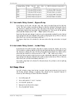
When the Ethernet module is fitted, the source of DMX and RDM can be assigned 

between the existing 5 pin DMX connector and the optional Ethernet connector. It is 

possible to select between the 4 possible combinations - refer to the following table. 

The left digit indicates the source of level information while the right digit indicates the 

source of RDM information. 


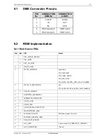
Summary of Contents for HPC AIRGAP

Page 1: ...HPC ...

Page 2: ...cturer could void the user s authority to operate the equipment DISCLAIMER Information contained in this manual is subject to change without notice and does not represent a commitment on the part of the vendor JANDS PTY LTD shall not be liable for any loss or damage whatsoever arising from the use of information or any error contained in this manual It is recommended that all service and repairs o...

Page 3: ...put 7 4 4 1 Changing the DMX Address 7 4 4 2 DMX Termination 7 5 0 Operation 8 5 1 Menu and Setting Adjustment 8 5 1 1 Root Menu 8 5 1 1 1 Changing the DMX Address 8 5 1 1 2Displaying the Software Version 8 5 1 2 Cap Function 11 5 1 3 Preheat Function 11 5 1 4 DMX Termination 11 5 1 5 DMX Data Loss 11 5 1 6 DMX Source 11 5 1 7 Automatic Relay Control Bypass Relay 12 5 1 8 Automatic Relay Control I...

Page 4: ...oisture and is not used in wet areas o Output sockets may have dangerous voltages present even when the channels are driven off Switch off the channel circuit breaker before connecting and disconnecting loads or replacing load lamps o The HPC should be properly mounted on a flat stable surface o Provide adequate ventilation during use Do not obstruct airflow around the vents o Do not run the power...

Page 5: ...y smoothly dim conventional incandescent loads Channels may be individually set to On Remote Switch Remote Dim or Off The HPC is controlled using DMX 512 A via a standard 5 pin socket on the front panel RDM functionality is provided to enable remote configuration and status readback via a suitable RDM controller The dimmed outlets and power entry are located on the rear panel The HPC provides easy...

Page 6: ...12 signals 7 ERROR LED Flashes in the presence of a fault In normal operation this LED should be off 8 IC LED The Internal Control LED Illuminates when control is internal ie not from the DMX 512 input 9 TERM LED Illuminates when the Terminate function is active 10 PHASE LEDs Three blue LEDs one for each phase indicate that the mains supply is available Note that all three LEDs should illuminate w...

Page 7: ...e blue phase power indicator LEDs A B and C are illuminated before connecting any loads If any of the phase LEDs are dim or off power down and remedy the fault before trying again If all is well power down and connect loads 4 3 Connecting Loads Switch off the channel circuit breaker before connecting and disconnecting loads Ensure any plugs are pushed firmly into their sockets The HPC dimmer circu...

Page 8: ...ected against extreme over voltages across any input pins and from any input to chassis The terminating resistor is not protected against over voltages Where the Ethernet option is fitted plug the Ethernet data into the front panel connector The source of control for DMX and RDM must be manually selected via the menu between the front panel DMX connector and the Ethernet connector refer to Section...

Page 9: ... is described in Table 2 5 1 1 Root Menu The root menu is displayed when the Exit button has been pressed sufficient times such that the DMX 512 start channel is displayed A number of functions are available at the Root Menu as detailed in the following sections 5 1 1 1 Changing the DMX Address The DMX address is the DMX 512 channel number that will be used to control HPC dimmer channel 1 HPC dimm...

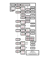
Page 10: ...ff Toggles DMX Termination function Sets cap value Hold to record the selected Scene Press to activate the Chase E E E E E E E E E E E Hold Menu E Cancel Exit RDM functionality Appears when Ethernet option fitted Affected by Deep Clear Global Preheat Preheat Value Sets preheat value System Checks E Signal Source DMX Ethernet DMX DMX Ethernet DMX Ethernet Ethernet Set DMX and RDM connection sources...

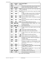
Page 11: ...e 240 240V nominal operation Pre OFF 50 Set the Preheat level Rlc byp Some channels have Bypass enabled and some don t Rlc Byp On Relay bypass will automatically activate Rlc Byp Off Relay bypass will not automatically activate Rlc iso Some channels have Isolate enabled and some don t rlc Iso On Relay Isolate will automatically activate rlc iso Off Relay Isolate will not automatically activate Chc...

Page 12: ...when in the Preheat menu If this is the case when the menu is entered the display will show This function is ignored for channels set On or to Switch 5 1 4 DMX Termination Any long DMX 512 data line must be terminated at the end for correct operation and the HPC provides this function Selecting the End option toggles the terminate function The TERM LED on the front panel indicates when the DMX 512...

Page 13: ...nu is entered the display will show The Bypass relay does not activate for channels where the Cap value does not equal 240 5 1 8 Automatic Relay Control Isolate Relay Each channel of the HPC includes relay that is used to Isolate the dimmer circuit The HPC includes an isolate activation mode that automatically activates the Isolate relay if the channel is dimmed to zero for more than about 60 seco...

Page 14: ...ered and to change the function of each channel between On Off Dim and Switch Refer to Section 9 2 for further information regarding the RDM commands implemented by the HPC In general a RDM controller should automatically discover the HPC and any other connected powered devices when it s turned on If not ensure RDM Discovery is enabled in the controller power up the HPC and re initiate Discovery o...

Page 15: ... controlled fan cooling As the internal temperature of the dimmer increases the fan speed increases The inlet and exhaust areas of the chassis must be kept clear while the HPC is on The HPC continuously monitors the internal heatsink temperature As the temperature approaches the rated maximum the internal processor attempts to reduce the heat build up by reducing the output levels If the temperatu...

Page 16: ...d correctly Reconfigure controller Controller does not conform to the published RDM standard Check specification for the controller version of RDM HPC RDM source not correctly set Change source setting 5 1 5 Intermediate equipment eg DMX splitter not RDM compatible Check specs of all other equipment RDM operation erratic DMX line un terminated Terminate the DMX line Poor DMX wiring Replace DMX wir...

Page 17: ... slots Additional venting area will serve to further reduce internal temperatures and will enhance the HPC s operational reliability HPC s may be stacked in racks without intervening rack spaces as long as the racks are adequately vented at the sides Racks of HPC s must be placed such that one rack does not breathe the hot exhaust of the rack next to it Allow at least 300mm 12 between racks unless...

Page 18: ...Blow clean the fan and internals with compressed air from left to right DO NOT spin the fan with compressed air the blades may break off 4 When the fan and internals are clean replace the lid and screws and re connect the power cable 8 3 Routine Maintenance Installed HPC s should be routinely flushed of dust at six to twelve month periods Touring HPC s may need a more rigorous maintenance routine ...

Page 19: ...akers Maximum Ambient Temperature 40ºC Maximum Altitude 2000m Over temperature cutout Soft limit starts at 92 C Full cutout at 100 C Control Signal ANSI E1 11 2004 DMX 512 A ANSI E1 20 2006 RDM DMX Input 5 pin AXR male female Snapshot Scenes 2 Test Function Level Individual Channels 100 All Channels 10 steps LED Indicators SIGNAL ERROR TERM IC Phases A B and C Ingress protection IP20 Internal Sepa...

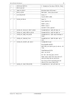
Page 20: ...DISC_UNIQUE_BRANCH DISC_MUTE DISC_UN_MUTE DEVICE_LABEL STATUS_MESSAGES Supported STS_OVERTEMP STS_PHASE_ERROR STS_DIM_PANIC STS_JANDS_NEUTRAL_EARTH_FAULT 0x8000 STATUS_ID_DESCRIPTION For STD_JANDS_NEUTRAL_EARTH_FAULT 0x8000 QUEUED_MESSAGE SUPPORTED_PARAMETERS PARAMETER_DESCRIPTION DEVICE_LABEL DEVICE_INFO DEVICE_MODEL_DESCRIPTION MANUFACTURER_LABEL FACTORY_DEFAULTS Will always report 0 on Get SOFT...

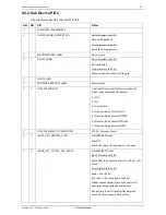
Page 21: ...x8080 Pdl 1 0x00 Off 0x01 On JANDS_HPC_DMX_PROTECT_MODE Pid 0x8082 Pdl 1 0x00 Off 0x01 On JANDS_HPC_DMX_LOSS_MODE Pid 0x8084 Pdl 1 0x00 Hold 0x01 Fade to Scene1 JANDS_HPC_PREHEAT_LEVEL Pid 0x8086 Pdl 1 0x00 Off 0x01 0x32 Level JANDS_HPC_OUTPUT_CAP_VALUE Pid 0x8088 PDL 0x1 Up to firmware rev 2 00 0x0 100 no output cap limit 0x1 0xC 5 Step From firmware rev 2 10 0x00 Full 240V 0x1 0xE 10V Step down ...

Page 22: ...ITY 7 personalities to controls dimmer channel mode see user manual for details 1 Off 2 On 3 Dmx Switch 4 Dimmer Relay Control FULL 5 Dimmer Relay Control BYPASS 6 Dimmer Relay Control ISOLATE 7 Dimmer Relay Control NONE DMX_PERSONALITY_DESCRIPTION Off On Dimmer Switch JANDS_HPC_PREHEAT_LEVEL Pid 0x8086 Pdl 0x1 0x0 Off 0x1 0x32 Level for sub device channel JANDS_HPC_OUTPUT_CAP_VALUE Pid 0x8088 PDL...

Reviews: