Getting Started
6
Revision 2.0c – 30 August 2013
HPC User Manual
4.0 Getting Started
The HPC would normally be rack mounted before any wiring is terminated. Refer to
Section 6.0 Installation for installation details.
4.1
Connecting Power
The HPC dimmer may be supplied with a mains inlet cable and multipin connector,
mains inlet cable and no connector, or with no inlet cable fitted. Refer to Section 7.2
for details on mains termination connection methods. Always connect to a supply that
is protected by fuses or circuit breakers at not more than the specified maximum.
Refer to Section 9.0 Technical Data and Specifications.
4.2
Powering Up
Turn on the power and check that the three blue phase power indicator LEDs A, B, and
C are illuminated before connecting any loads. If any of the phase LEDs are dim or off,
power down and remedy the fault before trying again.
If all is well, power down and connect loads.
4.3
Connecting Loads
Switch off the channel circuit breaker before connecting and disconnecting loads.
Ensure any plugs are pushed firmly into their sockets. The HPC dimmer circuit will drive
most incandescent loads as well as pinspots, fans, and dimmable fluorescent tubes.
Un-dimmable loads should not be driven from channels configured to dim (see section
4.3.1).
4.3.1
Changing the Channel Configuration
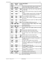
Each HPC channel may be independently configured to dim, switch, turn fully on, or be
fully off. To change a channel’s configuration:
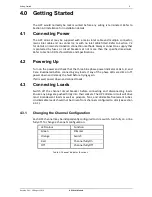
LED colour
Function
Green
Dimmer
Orange
Switch
Red
Channel fully On
Off
Channel fully Off
Table 1: Channel Indicator functions
Summary of Contents for HPC AIRGAP
Page 1: ...HPC ...

