background image

- 11 -

 JW-H61M-D3                                                                                                User's Manual 

S

FA

N

2

JD

V

I

H

D

M

I

_

PS/2

USB_LAN

USB

Chapter 3 Jumpers & Headers Setup

3.1 Checking Jumper Settings

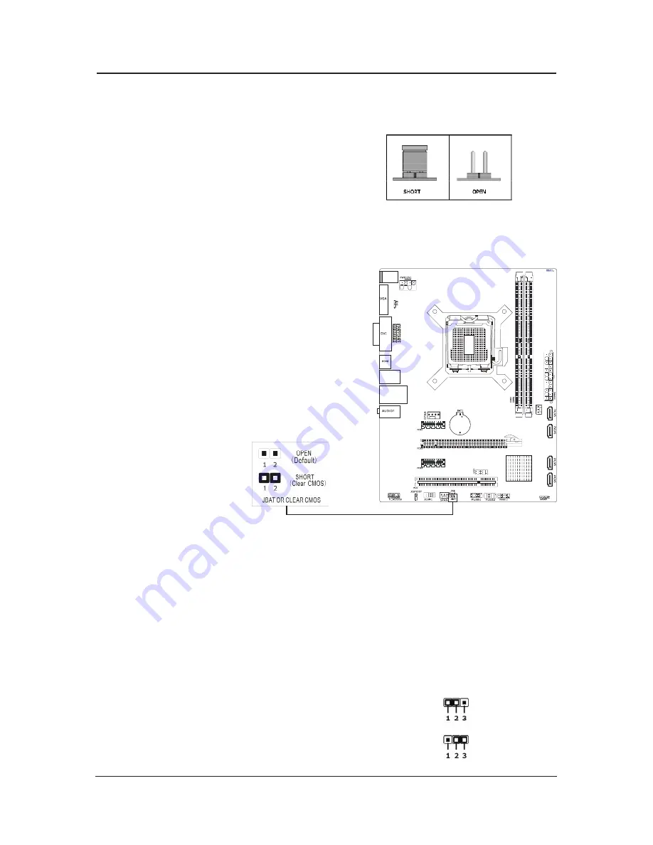
    • For a 2-pin jumper, plug the jumper cap on both 

      pins will make it CLOSE (SHORT). Remove the 

      jumper cap, or plug it on either pin (reserved for

      future use) will leave it at OPEN position. 

    • For 2-pin jumper, pin 1~2 can be shorted by 

       plugging the jumper cap in.


3.2 CMOS Memory Clearing Header

    The time to clear the CMOS memory occurs when (a) 

    the CMOS data becomes corrupted, (b) you forgot

    the supervisor or user password preset in the BIOS

    menu, (c) you are unable to boot-up the system 

    because the CPU ratio/clock was incorrectly set in the

    BIOS menu, or (d) whenever there is modification on 

    the CPU or memory modules.

   This header uses a jumper cap to clear the CMOS 

    memory and have it reconfigured to the default 

    values stored in BIOS.


   • Pins 1 and 2 opened

       (Default): Normal

       operation.

   • Pins 1 and 2 shorted:

       Clear CMOS memory.


To clear the CMOS memory and load in the default values:

    1. Power off the system.

    2. Set pin 1 and pin 2 shorted by the jumper cap. Wait for a few seconds. 

    3. Power on the system.

    4. For incorrect CPU ratio/clock settings in the BIOS, press <Del> key to enter the BIOS

        setup menu right after powering on system.

    5. Set the CPU operating speed back to its default or an appropriate value.

    6. Save and exit the BIOS setup menu.

3.3 Keyboard Power Function


Pin 1-2 short: Disabled power on by keyboard.

    Pin 2-3 short: Support power on by keyboard.

                    JKB:

Disable (Default)

Enable

Summary of Contents for JW-H61M-D3

Page 1: ...User s Manual Socket LGA1155 Processor Mainboard JW H61M D3 Rev 1 0 Mar 2011 Motherboard...

Page 2: ...ot guarantee the accuracy of the contents This manual is purely technical documentation without any hint or other meanings and we won t commit users misunderstanding of the typesetting error Our produ...

Page 3: ...tings 11 3 2 CMOS Memory Clearing Header 11 3 3 Keyboard Power Function 11 3 4 FAN Power Connectors 12 3 5 Front Panel Switches Indicators Headers 12 3 6 Additional USB Port Headers 13 3 7 Front Panel...

Page 4: ...duct Please check with the following list of accessories if there is any broken or missing part please contact your dealer or the local distributor SATA cables SATA power cables I O Shield User s manu...

Page 5: ...port 4 x USB 2 0 headers for additional 4 USB 2 0 ports by cables 1 x RJ45 LAN port 6 Channel Audio I O Internal I O Connectors 1 x 24 pin EPS Power connector 1 x 8 pin ATX 12V power connector 4 x SA...

Page 6: ...JW H61M D3 User s Manual 1 3 Mainboard Layout This picture is only for reference SFAN2 JDVI HDMI _ PS 2 USB_LAN USB...

Page 7: ...ects to multimedia devices of HDMI protocol USB The USB ports are used to connect USB 2 0 1 1 devices such as scanner speakers keyboard mouse hub digital camera joystick etc LAN The LAN port allows th...

Page 8: ...assis If the holes line up and there are screw holes you can attach the board with studs If the holes line up and there are only slots you can only attach with spacers Take the tip of the spacers and...

Page 9: ...ce it does not meet the required standards for the peripherals If you wish to set the frequen cy beyond the proper specifications please do so according to your hardware specifications including the C...

Page 10: ...MM 2 first as a dual channel operation To install system memory 1 Power off the computer and unplug the AC power cord before installing or removing memory modules 2 Locate the DIMM slot on the board 3...

Page 11: ...ces 2 5 1 Serial ATA Connectors Each SATA connector serves as one single channel to connect one SATA device by SATA cable 2 5 2 PCI and PCI Express slots Install PCI Express X16 graphics card into slo...

Page 12: ...set in the BIOS menu or d whenever there is modification on the CPU or memory modules This header uses a jumper cap to clear the CMOS memory and have it reconfigured to the default values stored in BI...

Page 13: ...ed reset switch which allows you to reboot without having to power off the system and thus prolonging the life of the power supply or system PWR_ON Black Power Switch Depending on the setting in the B...

Page 14: ...dio The headers conform to USB 2 0 1 1 specification Each USB header can provide two USB ports via an optional USB bracket Pin No Header HD Audio Definition AC97 Audio Definition 1 PORT1L Microphone_L...

Page 15: ...processing device It allows the transfer of audio from one file to another without the conversion to and from an analog format which could degrade the signal quality 3 8 JDVI_HDMI jumper and JME jumpe...

Page 16: ...into this connector If you would like to use an old power supply with only a 20 pin ATX main power connector then please plug the 20 pin ATX main power connector along with pin 1 and pin 13 PWR12V 12V...

Page 17: ...ecial features on or off etc 3 Enhancing your computer s behavior For example speeding up performance by turning on shadowing or cache 4 2 To Run BIOS Setup First access BIOS setup menu by pressing F1...

Page 18: ...The BIOS setup screens and descriptions illustrated in this manual are for your reference only and may not completely match with what you see on your screen This chapter were based mainly on the mode...

Page 19: ...you specify usually the current time in the format of Hour Minute and Second Aptio Setup Utility Copyright C 2010 American Megatrends Inc Main Advanced Chipset Boot Security OverClock Save Exit BIOS I...

Page 20: ...ed setting Aptio Setup Utility Copyright C 2010 American Megatrends Inc Advanced ACPI Settings Enable ACPI Auto Configuration Enable Hibernation ACPI Sleep State Lock Legacy Resources Disabled Enabled...

Page 21: ...onfiguration Click Enter key to enter its submenu Aptio Setup Utility Copyright C 2010 American Megatrends Inc Advanced Intel R Core TM i7 2600 CPU EMT64 Max Processor Speed Min Processor Speed Proces...

Page 22: ...fectching of adjcent cache lines Intel Virtualization Technology When enabled a VMM can utilize the additional hardware capabilities provided by Vanderpool Technology CPU C3 Report Setting CPU C3 ACPI...

Page 23: ...t F1 General Help F7 Previous Values F8 Fail Safe Values F9 Optimized Defaults F10 Save Exit ESC Exit Version 2 02 1205 C Copyright 2010 American Megatrends Inc Power On By PS 2 Keyboard When setting...

Page 24: ...DIMM Voltage VTT Voltage PCH Voltage VBAT Voltage Smart Fan Configuration Fan PWM Value 45 o C 30 o C 2276 RPM N A 1 192 V 1 512 V 1 040 V 1 024 V 3 264 V Manual Mode 255 Smpart Fan Configuration Sele...

Page 25: ...r 1024 MB DDR3 1333 1024 MB DDR3 1333 0 MB DDR3 1333 1024M Enabled Disabled PEG IGD 96M Enabled Disabled Low MMIIO resources align at 64MB 1024MB Select Scree Select Item Enter Select Change Opt F1 Ge...

Page 26: ...allows users to enable or disable the SATA controller Serial ATA Controller 0 Available options Disabled Enhanced Compatible Serial ATA Controller 1 Available options Disabled Enhanced Compatible SATA...

Page 27: ...ilable options Disabled Enabled Press Esc key to return to Chipset menu ME Subsystem Click Enter key to enter its submenu Aptio Setup Utility Copyright C 2010 American Megatrends Inc Chipset Serial Po...

Page 28: ...t Change Opt F1 General Help F7 Previous Values F8 Fail Safe Values F9 Optimized Defaults F10 Save Exit ESC Exit Version 2 02 1205 C Copyright 2010 American Megatrends Inc Setup Prompt Timeout Number...

Page 29: ...orget your password If you forget the password you will have to open the computer case and clear all information in the CMOS before you can start up the system But by doing this you will have to reset...

Page 30: ...Copyright C 2010 American Megatrends Inc Main Advanced Chipset Boot Security OverClock Save Exit Over Clock Configuration CPU Configuration Memory Configuration Graphics Configuration OC Voltage Cont...

Page 31: ...ubmenu The following items Setting the memory voltage Aptio Setup Utility Copyright C 2010 American Megatrends Inc OverClock Intel Graphics Configuration Graphics Core Ratio Limit Graphics Voltage 1 1...

Page 32: ...ect No or press ESC and return to the main menu Save Changes and Reset Select Save Changes and Reset and select Yes and press Enter to save the changes made to the BIOS and restart Select No or press...

Page 33: ...double click My Computer double click CD ROM drive or click Start click Run type X Setup exe assuming X is your CD ROM drive Mainboard Driver installation Utility Kaspersky Internet Security 2011 User...

Page 34: ...m the Drivers MENU you may make 5 selections 1 INTEL Chipset Installation Utility 2 INTEL Chipset VGA Graphics Driver 3 Onboard LAN Driver 4 Realtek HD Audio Driver 5 PCI Simple Communication Controll...

Page 35: ......

Page 36: ......

Reviews: