←
Top Left Mounting Indicator
Power Pack Mounting Template
Use this template to drill holes for mounting the power pack
Top Right Mounting Indicator
→
FOR YOUR SAFETY - This product must be installed and serviced by a contractor who is licensed and
qualifi ed in pool equipment by the jurisdiction in which the product will be installed where such state
or local requirements exist, the maintainer must be a professional with suffi cient experience in pool
equipment installation and maintenance so that all of the instructions in this manual can be followed
exactly. Before installing this product, read and follow all warning notices and instructions that accompany
this product. Failure to follow warning notices and instructions may result in property damage, personal
injury, or death. Improper installation and/or operation will void the warranty. Improper installation and/
or operation can create unwanted electrical hazard which can cause serious injury, property damage, or
death. Turn off all circuit breakers required in order to prevent the possibility of electric shock.
Installation and operation manual (H0470600), available online at
www.ZodiacPoolSystems.com or by calling:
USA: 1-800-822-7933 | CANADA: 1-888-647-4004 | AUSTRALIA: 1800-688-552
Installing the Power Pack
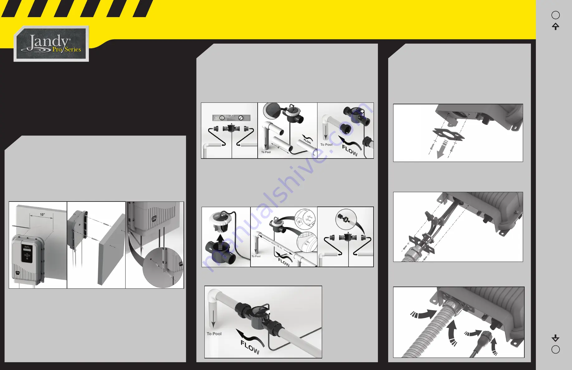
1. Ensure placement of the cell and the power pack will meet all the installation
requirements outlined in the Installation Manual.
2. Determine the desired location on the wall to mount the Power Pack.
3. Mark and drill the top two holes in the wall, using the template provided on
the right hand side of this Quick Start Guide. The distance from the center of
the two holes is 10 inches. Use a level and the template to locate the exact
position of the holes.
Installing the Cell
1. Determine the desired location for the cell as the last piece of equipment before
the return inlet to the pool, on a pipe segment at least 16 inches long. The cell
must be mounted upright on pipe which runs within ± 5º of level (parallel to the
ground). The cell cannot be mounted on a vertical, or sloping pipe.
2. Make the appropriate cuts in the pipe where you will be installing the cell. The
gap between the cuts should be 6 inches for a standard installation and 14.5
inches for the retrofi t installation.
Wiring the Power Pack to the Power Source
1. Wire power pack to pool pump power source using 12
AWG (3.3 mm
2
) insulated wire and conduit. Wire the power
pack to the LOAD side of the pool pump timer relay so that
the chlorinator can only come on when the pool pump is
turned on. See Wiring Diagram.
2. Remove the electrical mounting plate that feeds the power
cable to the power pack.
3. Feed the power cable through the mounting plate.
4. Connect the conduit to the mounting plate.
5. Make the wire connections. Note: The green (or Green/
Yellow) wire should be connected to ground.
6. Place all of the wire connections and cables inside the
power pack and secure the mounting plate tightly.
7. Plug the cell into the power pack.
3. Remove the cell from the housing and plumb the housing into the pipe, making
sure that the fl ow indicator arrows on the housing match the fl ow direction of
the water. It must be mounted upright and horizontally, with the cable exiting the
top and facing upward. Pipes must be clean and dry before gluing.
4. Let the system dry per instructions provided by the glue manufacturer. When
the glue is dry, start the system and check for proper water fl ow.
4. Drive the screws into the holes and hang the Power Pack from the top two
holes of the backplate.
5. With the Power Pack in place, mark the position of the bottom two holes.
6. Remove the Power Pack, drill the bottom two holes and place the screw
anchors in position.
7. Mount the Power Pack by hanging it from the top two screws already in
place, then drive in the two bottom screws to complete the installation.
1
2
3
Standard Installation
Must be horizontal with
cell window facing up
Retrofi t Installation


