background image

Page 13 

ENGLISH


Jandy

®

 Pro Series, Hi-E2

®

 and Hi-E2R Gas-Fired Heater   

|

   Installation & Operation Manual

SPA

Cuve Thermal

POOL

Piscine

OFF

Arrét

W

W

W

BK

Y/BK

Y

R

Y

Y

Y

BK

W-R

W-BK

R

BK

BK

L1

G

N

W

BK

W

W

F1
F2

24V

FC

IGNITION

CONTROL

Commande

d’allumage

W

R

W

P

Y/BK

BR

Y

Y/BK

BR

Y

IGN240

L1

L2

IGN/FS

TH
VAL
GND

ELECTRONIC TEMP CONTROL

Régulation électronique de

température

PV

MV 24V

PSW

WATER TEMP

SENSOR

Capteur de

température de l’eau

REMOTE CONNECTOR

Connecteur à distance

LIMIT

Limiteur

LIMIT

Limiteur

PRESSURE SWITCH

(WATER)

Manostat (eau)

ELECTRICAL

FUSE

Fusible

FIREMAN

SWITCH

CONNECTION

Interrupteur

pompier

TRANSFORMER

Transformateur

IGNITER

Allumeur

VENTURI. PRES. SWITCH

Interrupteur à pression

différentielle

VENT LIMIT

Limiteur de débit

BURNER LIMIT

Limiteur du brûleur

(MANUAL RESET)

(Remise à zéro)

(SINGLE USE)

(Uniservice)

GAS VALVE

Soupage de gaz

IF ORIGINAL WIRE SUPPLIED WITH HEATER MUST BE REPLACED, APPLIANCE WIRING

MATERIAL RATED FOR 105°C MUST BE USED.

Si le fil d’origine fourni avec le chauffee-eau doit être remplacé, utiliser un fil pour appareils

électriques à tolérance nominale de 105°C.

FACTORY WIRED 24V

FACTORY WIRED 115V

FIELD WIRED 115V

Cáblè en usine - 24V

Cáblè en usine - 115V

Cáblè sur le terrain - 115V

BK-

W-

BR-

R-

Y-

G-

P-

Black 

White 

Brown 

Red 

Yellow 

Green 

Purple 

(Noir)

(Blanc)

(Brun)

(Rouge)

(Jaune)

(Vert)

(Mauve)

GY-

 Gray

(Gris)

COMB.

FAN

Ventilateur

à

combustion

115V

60Hz

H0205500F

IGN120

IND

W

W

BK

GY

R

BR

TR

TH

DIGITAL IGNITION CONTROL

BK

Hi-E2

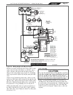
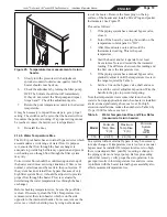
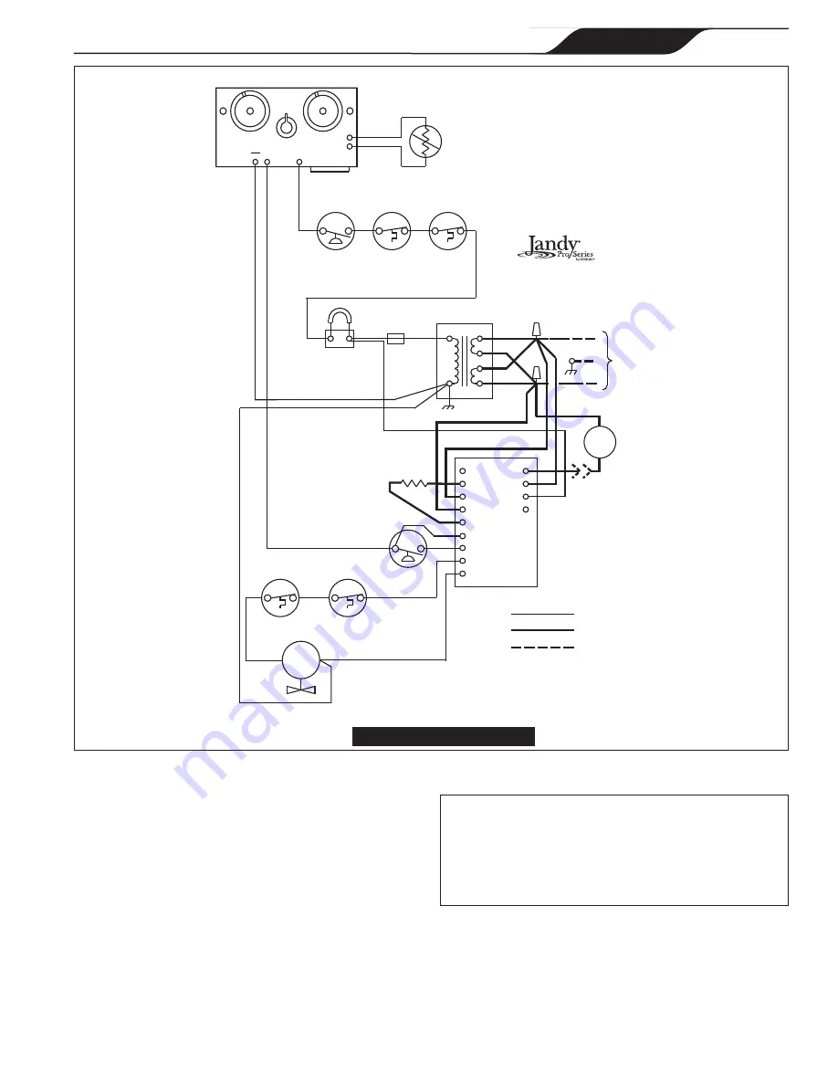
Figure 15.  Wiring diagram, Hi-E2 pool heater.

The Hi-E

2

 requires electrical power from a 115V, 60 Hz 

source. Do not connect this heater to a 230VAC power 

source. Wiring connections must be made exactly as 

shown in the wiring diagram, see Figure 15. Grounding 

must be provided as required by the prevailing electrical 

code.

Connect wiring inside the junction box, which is on the 

right side of the heater and is accessible through the door 

opening. Line voltage connections must be made within 

this box. A labeled green grounding screw is provided in 

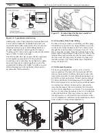
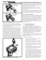
the junction box for a grounding wire. See Figure 14.
Wiring should include a means to prevent operation of 

the heater when there is no water flow. This is typically 

done with a time clock “Fireman’s Switch” as discussed 

in Section 2.10.3.

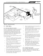
2.10.2 Bonding

CAUTION

To prevent premature failure of the appliance resulting 

from stray voltages and voltage differentials, the heater 

must be bonded to other equipment which is part of 

the pool plumbing system with a solid copper wire not 

smaller in diameter than 8 AWG, 6 AWG in Canada.

Zodiac

®

 requires that the appliance be connected to a 

"bonding loop" that includes all electrical equipment in 

the system and on the equipment pad.  Bonding lugs must 

be connected with a solid copper wire not smaller than 

8 AWG (6 AWG in Canada).  Failure to do so will void 

warranty. 

Summary of Contents for HI-E2

Page 1: ...ion and or operation can create carbon monoxide gas and flue gases which can cause serious injury property damage or death For indoor installations as an additional measure of safety Zodiac Pool Syste...

Page 2: ......
Page 3: ...tion 17 2 12 2 Start up 17 2 12 3 Condensate 17 2 12 4 Gas Pressure 18 2 12 5 Adjustment of Water Pressure Switch 18 2 12 6 Water Temperature Rise 19 Section 3 Operating Instructions 19 3 1 Start Up P...

Page 4: ...arranty The Hi E2 is sold with a limited factory warranty A copy of the warranty is included in a plastic bag inside the heater The warranty does not cover damage caused by improper installation opera...

Page 5: ...building codes for additional requirements CAUTION When pool equipment is located below the pool surface a leak from any component can cause large scale water loss or flooding Zodiac Pool Systems Inc...

Page 6: ...of the heater The correct size drill bit is usually provided with the concrete screws when purchased Place a screw in each of the holes and fasten the heater to the equipment pad see Figure 2 Do not o...

Page 7: ...and Ventilation Air Model Required net free area in square inches sq cm for each of 2 openings one 1 near ceiling and one 1 near floor Directly Through an Exterior Wall Through Horizontal Ducts 350 88...

Page 8: ...boratory NRTL as being compliant with the applicable requirements of the Underwriters Laboratories UL standard for safety for Venting Systems for Gas Burning Appliances Categories II III and IV ANSI U...

Page 9: ...on inlets etc In the United States this distance must be at least 4 feet 1 21 m In Canada it must be at least 10 feet 3 04 m five 5 elbows Per Table 3 Only 16 feet of 4 vent pipe would be allowable wh...

Page 10: ...e it can be disposed of properly Support vent piping with suitable hangers so its weight does not bear on the heater or building penetration and so that piping joints are not strained Support horizont...

Page 11: ...wer A package of limestone gravel neutralizer is provided with the condensate assembly Remove the neutralizer from the packing and spread evenly throughout the tray and around the properly placed tube...

Page 12: ...s control during testing When the heater is started check the supply pressure to verify that it is adequate during heater operation Undersize piping a restrictive fitting or an undersize gas meter can...

Page 13: ...aune Vert Mauve GY Gray Gris COMB FAN Ventilateur combustion 115V 60Hz H0205500F IGN120 IND W W BK GY R BR TR TH DIGITAL IGNITION CONTROL BK Hi E2 Figure 15 Wiring diagram Hi E2 pool heater The Hi E2...

Page 14: ...ff from a remote location Contact your local Jandy Pro Series distributor for information on the AquaLink RS control system to fit your back yard recreational needs An interrupt on off type remote can...

Page 15: ...the brass fitting 5 Remove the temperature control sensor by removing the retainer bracket and its cap screws 6 Disconnect the limit switch wires from the limit switches The limit switches and the sho...

Page 16: ...d A pressure relief valve is not supplied with the Hi E2 All equipment installations need to be in accordance with the manufacturers instructions To install a pressure relief valve 1 Remove the 3 4 br...

Page 17: ...in the system when installing a PRV Any pressure relief valve installed must comply with provisions of the standard described in ANSI Z21 22 for the United Sates or CSA 4 4 in Canada Some local codes...

Page 18: ...its operation and settings as outlined in the maintenance section of this manual 2 12 4 1 Step down Gas Pressure Regulator The step down regulator does not change requirements for gas supply piping o...

Page 19: ...tem or a larger pump Before proceeding with either remedy verify proper heater operation Low gas input results in low temperature rise and vice versa A problem with the heater internal bypass assembly...

Page 20: ...de of the service door and also on the inside of the control compartment door Lighting instructions are as follows 1 Turn off all electrical power to the heater at the main junction box 2 Open the con...

Page 21: ...factor of the pool water between 7 4 and 7 6 See Table 7 for guidelines on other chemical measurements 3 4 2 Spas The proper chemical balance in spa water is more critical than in a swimming pool hea...

Page 22: ...se spas or hot tubs 3 4 2 2 Saturation Index PH Total Alkalinity TA temperature Calcium Hardness and Total Dissolved Solids TDS play a role in whether the water is either corrosive or scale forming Th...

Page 23: ...the 78 F 26 C level before expected usage keeping in mind to allow enough lead time for the water to reach the desired temperature 6 During the winter shut down the heater by following the lighting a...

Page 24: ...technician when inspecting and servicing the heater To reactivate the heater in the spring have a qualified professional technician reassemble the heater as follows 1 Attach the pressure switch fitti...

Page 25: ...lter and strainers aren t clogged that there are no mis positioned water valves that the gas or electric power supplies aren t shut off and that time clocks are properly adjusted Also be sure that the...

Page 26: ...ixture monitors the flame and controls the combustion blower and gas valve When the temperature control requires heat the ignition control starts the blower providing a pre purge of the combustion cha...

Page 27: ...tings or similar devices may be the problem Voltage outside of the above range may be due to poor wiring poor connections other loads such as air conditioning compressors or to an electric utility com...

Page 28: ...ectrical power or setting the control to Off 4 5 2 3 Fireman Switch and External Interlocks Probe for voltage at point 3 the other connection of the terminal block which has a white wire connected to...

Page 29: ...l for heat Observe that the normal sequence takes place by noting blower operation the glow of the igniter through the combustion chamber sight glass and then voltage at point 8 If the blower does not...

Page 30: ...on heater The manometer will read zero until the gas valve opens and then it will indicate the gas orifice differential The gas orifice differential should be 4 0 0 3 WC for a unit at sea level See s...

Page 31: ...other elevations Note that when the heater is operated with the gas valve off it will eventually lock out because the ignition control does not sense flame Normally there will be enough time to obtai...

Page 32: ...ockage in the combustion air supply system Correct any such problems and verify normal operation by returning to the venturi system checkout procedures Pressure readings will be less if the heater is...

Page 33: ...eration Check for blockage by disconnecting drainage tubes at the collector and the vent diffuser Probe these openings with a tool or wire hook to dislodge any debris Limestone gravel neutralizer is r...

Page 34: ...04300 18 By Pass Valve Assembly 350 R0304400 19 Flow Control Cap 350 S0076700 20 By Pass Valve Gasket 350 R0011400 21 By Pass Valve Spring 350 R0304500 22 By Pass Valve Rod 350 R0304900 23 By Pass Val...

Page 35: ...oor Exhaust Grill 350 R0348400 57 Indoor Vent Collar not shown 350 R0307900 58 Condensate Trap Assembly 350 R0303300 59 Limestone Gravel 350 R0306200 60 Condensate Trap Cover 350 R0213300 Venturi Hard...

Page 36: ...ired Heater Installation Operation Manual 42 46 65 66 12 45 44 43 55 56 86 40 30 38 41 83 84 30A 34 32 33 39 36 37 35 6 4 10 1316 48 85 54 1 75 81 87 53 50 51 52 17 14 3 18 23 15 29 49 8 9 2 5 58 60 6...

Page 37: ...Page 37 ENGLISH Jandy Pro Series Hi E2 and Hi E2R Gas Fired Heater Installation Operation Manual NOTES...

Page 38: ...Page 38 ENGLISH Jandy Pro Series Hi E2 and Hi E2R Gas Fired Heater Installation Operation Manual NOTES...

Page 39: ...Page 39 ENGLISH Jandy Pro Series Hi E2 and Hi E2R Gas Fired Heater Installation Operation Manual NOTES...

Page 40: ...CA 92081 1 800 822 7933 www jandy com ZODIAC is a registered trademark of Zodiac International S A S U used under license All other trademarks referenced herein are the property of their respective ow...

Reviews: