Page 14
9. Replace the service door.
10. Turn the rocker switch to ON.
11. Set temperature control to against the
TEMPLOK tab. The main burner should
light. Until the water reaches a temperature
of about 21°C (70°F), it is normal to have
some water accumulating in the base of the
heater.
12. Set the time clock, if one is installed.
3C-2. Relighting the Heater
If the pilot goes out, repeat steps 5 through 7 in
Section 3C-1.
3C-3. Shut-Down Procedure
1. To turn the main burner off, turn the rocker
switch to OFF.
2. To turn the heater off (including the pilot),
press the red button on the gas valve.
3C-4. Putting the Heater In Operation
(Commissioning)
1. When the heater has lit, remove the service
door and check all gas connections for
soundness with leak detection fluid.
2. Check the manifold (burner) pressure setting
and adjust as necessary (see Table 1).
3. Start the adjustment procedure with the
heater cold, on full load, and with the tem-
perature control set at maximum. This will
ensure, as far as possible, that thermostatic
shutdown does not interfere while the pres-
sure is being checked and adjusted.
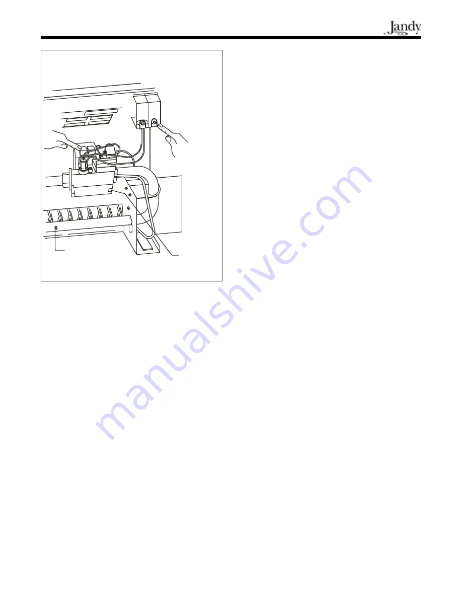
4. Remove the blanking screw in the manifold
(burner) setting pressure test nipple (see
Figure 18) and securely connect a suitable
gas pressure gauge.
5. Light the heater and allow it to operate for
about 15 minutes to stabilize the burners.
6. Check the pressure and adjust it for the
appropriate heater size. The manifold
At the same time repeatedly push the button
of the ignitor (see Figure 18) to produce a
spark at the pilot burner. When the pilot has
lit, keep the button on the gas valve fully
pushed in for another 30 seconds.
6. Release the white button and verify that the
pilot is lit.
7. If the pilot burner does not remain lit when
the button is released, press and release the
red button. Wait at least 3 minutes and then
repeat the lighting procedure from step 5.
8. If the pilot cannot be established, check that
the pilot burner flame correctly envelops the
thermocouple tip by 10 to 13 mm. If not,
check that the pilot adjustment screw on the
gas control (see Figure 17) is fully un-
screwed, then turn it one turn back in. Check
that the thermocouple lead connections at the
gas control and at the overheat thermostat
are clean and secure. Repeat from step 5.
Figure 18. Lighting the pilot.
Manifold
Pressure
Setting
Adjustment
Pressure Test
Nipple with Blanking
Screw


