Page 19
Legacy
™
Model LRZM Pool/Spa Heater Installation and Operation Manual
CAUTION
In order to prevent property damage or injury, be
sure that none of the wires are in contact with a
sharp edge or a hot surface.
ATTENTION
A
fi
n d'empêcher des dégâts matériels ou des bles-
sures, assurez-vous qu'aucun des
fi
ls n'est en con-
tact avec un bord tranchant ou une surface chaude.
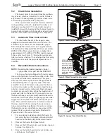
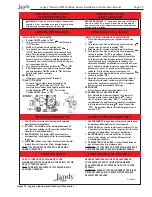
23. Install the return header side cover plate on the
right side of the unit.
24. Install the I/O header side cover plates, top and
bottom on the left side of the unit.
25. Replace the front panel (door).
5.5
Connections at Heater
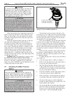
The Legacy heater has a standard two (2) inch
water header and coupling design. With this feature,
only nominal two inch PVC or CPVC may be connect-
ed to the heater. However, by installing the appropriate
pipe adapters and two short pieces of two inch plastic
pipe (supplied by the installer), any size existing pipe
may be
fi
tted to the heater.
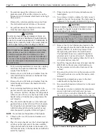
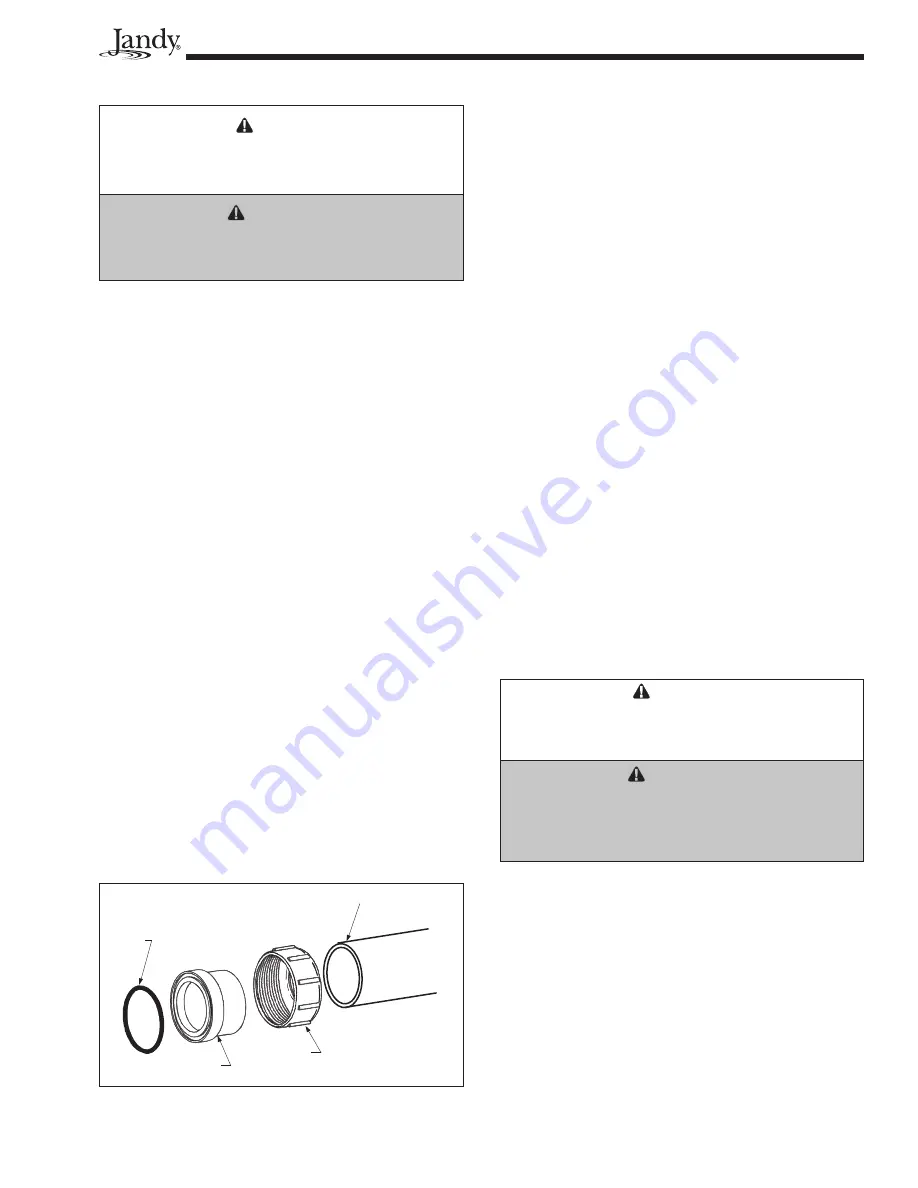
To connect a section of 2” PVC or CPVC pipe to
the heater,
fi
rst slip a coupling nut onto the pipe. Then
prepare the end of the pipe with the proper PVC/CPVC
primer and glue. Follow the manufacturer’s instruc-
tions provided with the primer and glue for preparation
procedures and curing times. Apply the slip-
fi
t side of
the coupling to the end of the pipe. Allow the glue to
cure completely. Set the o-ring into the groove on the
face of the coupling. Slide the coupling nut up to the
coupling and tighten it to the threaded connection on
the header (see Figure 12).
5.6
Pressure Relief Valve
A pressure relief valve (PRV) is recommended in
all installations, and is mandatory in any installation
in which the water
fl
ow can be shut off between the
heater outlet and the pool/spa.
A pressure relief valve is not supplied with the
Legacy heater. However, it is recommended that a
pressure relief valve be installed and may even be
required by local codes. Be sure to check any appli-
cable installation codes in your area to determine
whether a pressure relief valve is required. See Section
11.2 (Parts List) of this manual for the appropriate kit
part number.
The maximum working pressure of this heater
is 75 psi. Be sure to take into consideration the
maximum allowable pressure of the other components
in the system when selecting a PRV. Any pressure
relief valve installed must comply with provisions of
the standard described in ANSI Z21.22 for the United
States or CSA 4.4 in Canada.
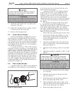
Follow these steps to install a pressure relief valve:
1.
To protect the threads while drilling, screw the
brass adapter (included with the Jandy PRV kit)
into the blind threaded hole on the top of the
inlet/outlet header.
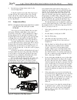
2.
Using the countersink in the center of the blind
hole as a guide, drill a 1/4 inch hole through the
plastic (see Figure 13).
3.
Open the hole by reaming it with a 3/8 inch drill
bit.
4.
Open the hole again by reaming it with a 1/2 inch
drill bit.
CAUTION
Initially drilling a 1/2" hole without reaming may
cause the bit to "grab" on the plastic. This may
cause personal injury or damage the plastic header.
ATTENTION
Si vous commencez à percer le trou de ½" sans
alésage préalable, la mèche risque de « mordre »
dans le plastique. Vous risquez de vous blesser ou
d’endommager le tuyau collecteur de plastique.
5.
Remove the brass adapter and clean the cuttings
out of the hole.
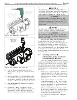
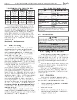
6.
Install the rubber washer at the bottom of the
hole (see Figure 14).
7.
Thread the adapter into the hole and tighten so
that it seals against the rubber washer.
8.
With a permanent marker, place a mark on the
adapter so that the mark faces the same direction
as the water connections on the header.
9.
Remove the adapter from the hole.
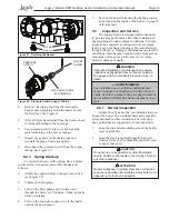
Figure 12. Piping to Heater
O-RING
TAILPIECE
UNION NUT
PVC OR CPVC PIPE
Summary of Contents for Legacy LRZM
Page 2: ......


