LX and LT Low NOx Pool/Spa Heater
Page 37
The system operates with a balanced combina-
tion of natural and induced draft. Air and gas are
pulled into the burner venturis where they are mixed
and conveyed to the combustion chamber. The
combustion process produces heat and creates a
negative pressure or "draft" condition. A small
amount of secondary air is pulled into the chamber
through holes and openings provided for that purpose.
Hot combustion products pass through a highly
efficient heat exchanger, where water absorbs most of
the heat. Cooler products continue on and are pulled
into the combustion blower, which exhausts them and
stabilizes system flow. Exhaust is directly to the
outdoor air through a grill, or for indoor heaters,
through vent piping.
10.3 Special Service Issues - Premix
Combustion System
10.3.1 System Operation
Premix combustion systems are less tolerant of
fuel and air imbalance than lesser technologies. Fuel
gas properties, incorrect supply or manifold pressure or
draft problems affect their operation and reliability. If
fuel gas heat content is low, combustion is "lean" and
tends to be unstable. Flames may lift off the burner,
causing outage. If heat content is high, "rich" combus-
tion results, with low, hot flames that can overheat the
burners. Likewise, low gas supply or manifold pressure
results in lean, unstable combustion and high manifold
pressure results in a rich process and hot burners.
"Draft", the negative pressure in the combustion
chamber pulls air through the burners and the "draft"
holes beneath the burners. Air is also pulled in through
various cracks or openings at the edges of the com-
bustion chamber and burner assembly. It is important
to control draft by assuring that fit and sealing remain
in "factory" condition. Service operations involving
burner, heat exchanger or flue collector removal must
be conducted with this in mind.
10.3.2 Field Service and Adjustment
As with all gas-fired appliances, the first order of
business is to verify correct gas type, supply pressure
and manifold pressure, as specified on the heater
rating plate and in other sections of this manual. If the
fuel supply differs greatly from "average", it may be
necessary to replace gas orifices. Contact the Jandy
Technical Service Group at (707) 776-8200 for
assistance in that situation.
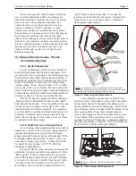
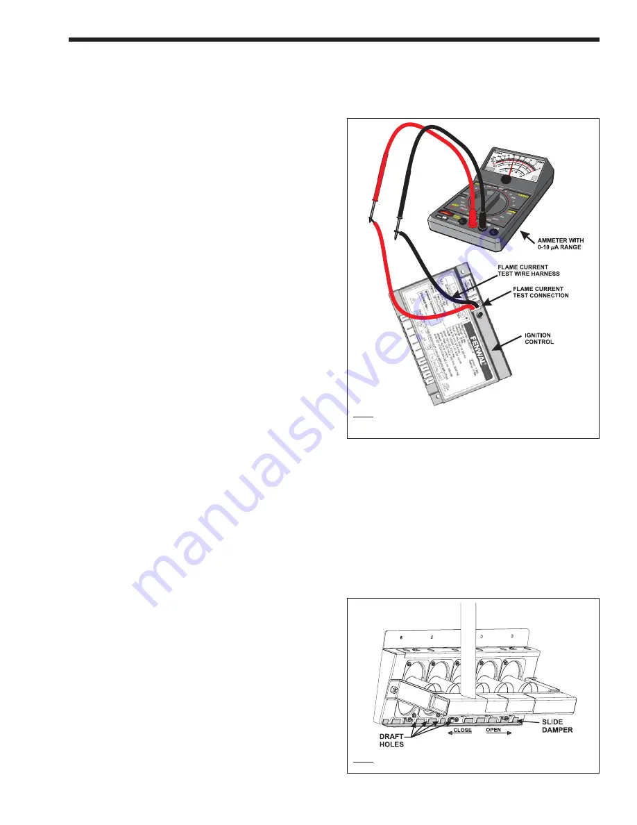
The most effective and convenient procedure for
evaluation of system operation is measurement of the
"flame signal". It can be measured at the pin connec-
tions on the ignition control next to the red LED lamp.
A two-pin wire harness, available from Jandy Techni-
cal support, and a microammeter with a zero to 10
microamp scale are ideal for reading the flame cur-
rent. If flame current is less than 0.7
µ
amps the
ignition control shuts down the system. Normally the
signal is five to seven
µ
amps. Figure 37 illustrates
flame signal measurement.
To accommodate construction or field factors
affecting draft, a slide damper is provided beneath the
burner inlets. Figure 38 illustrates this damper in its
factory-adjusted position for natural gas, which is half
open. Propane units are shipped with the damper in the
fully open position. If gas type and pressures are
correct, the damper can be used to adjust the system.
"Lean" flame-lifting conditions can be corrected by
opening the damper. This makes combustion chamber
pressure less negative. Likewise, "rich" hot flames can
be corrected by further closing the damper.
Figure 37. Measuring the Flame Current
NOTE: This illustration is only a representation of the measurement.
When the measurement is taken, the ignition control must be completely
connected to the heater and the heater must be running.
Figure 38. Slide Damper Draft Adjustment
NOTE: Natural gas burner tray shown with slide damper in factory
installed position.


