Page 16
LXi
™
Pool/Spa Heater Installation and Operation Manual
Section 4. Gas Connections
4.1
Gas Supply and Piping
Review the following general instructions before
continuing the installation.
WARNING
The LXi pool and spa heaters are designed for use
with either natural gas or LP gas. Check the rating
plate on the inner panel to be sure that the heater is
designed to use the type of gas being supplied.
DO
NOT ATTEMPT TO CONVERT THIS HEATER FOR
USE WITH ANY OTHER TYPE OF FUEL.
AVERTISSEMENT
Les appareils de chauffage à faibles émissions
LXi pour piscines et cuves thermales sont conçus
pour être utilisés avec du gaz naturel ou du gaz de
pétrole liqué
fi
é (GPL). Véri
fi
ez l’information inscrite
sur la plaque signalétique du panneau intérieur pour
vous assurer que l’appareil est conçu pour le type
de gaz fourni.
NE PAS ESSAYER DE CONVERTIR
CET APPAREIL À UN AUTRE TYPE DE GAZ.
1.
Gas piping installation must be in accordance
with the latest edition of ANSI Z223.1 and all
local codes. In Canada, the installation must be in
accordance with CAN/CSA B149.1 and all local
codes that apply.
2.
Check the gas supply to be sure that it is the same
as the gas indicated on the heater's rating plate.
LXi heaters, as shipped from the factory, are set
to operate within the low altitude range. Follow
the instructions in
Section 10.4.3
to adjust the
heater for high altitude.
CAUTION
Permanent damage to the gas valve will occur if the
following procedures are not followed.
ATTENTION
Vous endommagerez la soupape de gaz si vous ne
respectez pas les procédures suivantes.
3. Use
the
fi
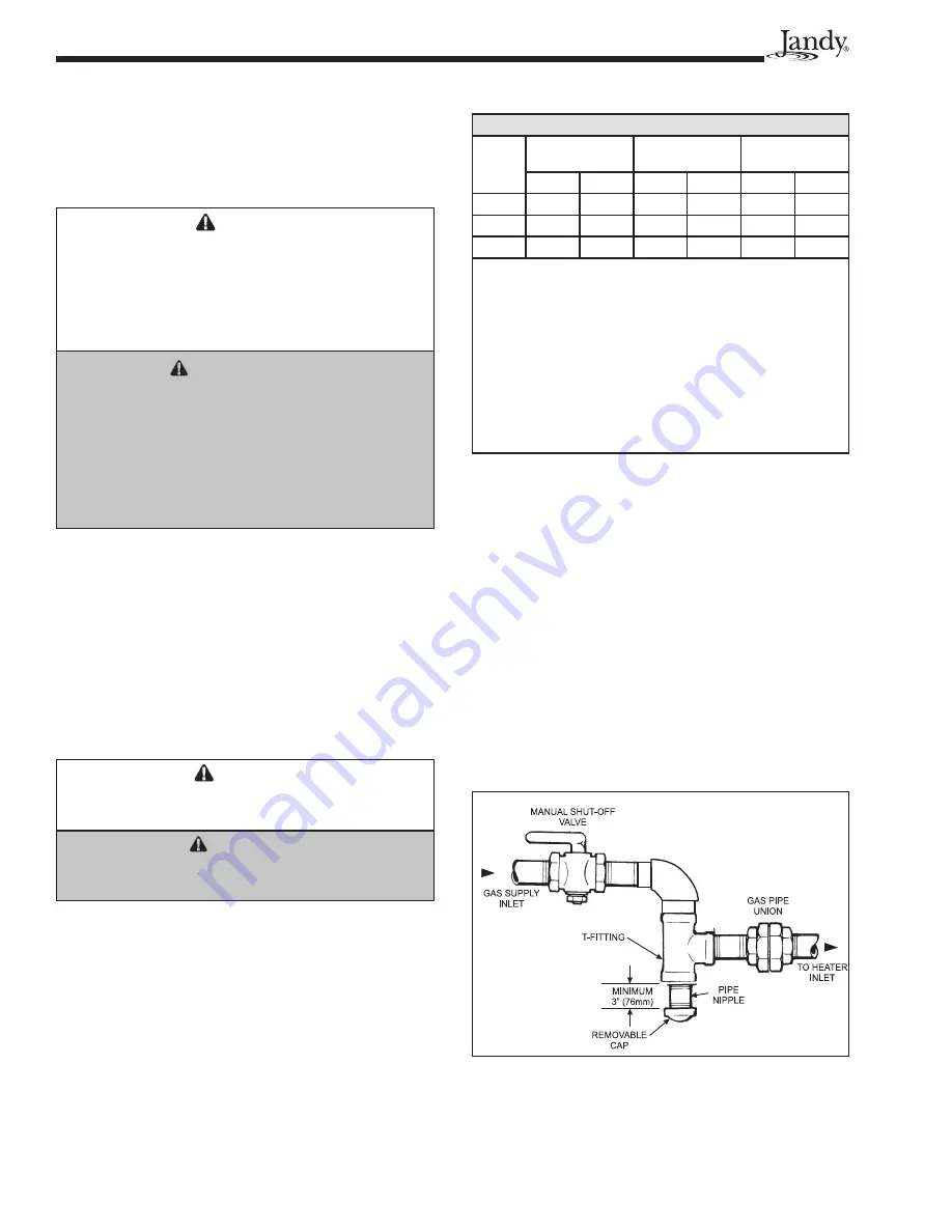
gures in Table 5 to size the gas inlet
piping from the gas meter to the heater. Check all
local codes for compliance before installing the
heater.
Table 5. Supply Gas Pipe Size Requirements*
Distance from Gas Meter
Heater
Size
0-50 feet
(0-15 m)
50-100 feet
(15-30 m)
100-200 feet
(30-60 m)
in.
mm
in.
mm
in.
mm
250
1
25
1-1/4
32
1-1/4
32
300
1-1/4
32
1-1/4
32
1-1/2
38
400
1-1/4
32
1-1/2
38
1-1/2
38
Notes:
*1. These numbers are for natural gas (0.65 Sp. Gr.) and
are based on 1/2 inch (3.45 kPa) water column pressure
drop. Check supply pressure with a manometer, and local
code requirements for variations.
For LP gas, reduce
pipe diameter by one size, but maintain a minimum
3/4" diameter.
2. Check supply pressure and local code requirements before
proceeding with work.
3. Pipe
fi
ttings must be considered when determining gas
pipe sizing.
4.
Install a sediment trap (drip leg) ahead of the gas
controls. See Figure 9. Fit the trap with a thread-
ed cap which can be removed for cleaning.
5.
Install a manual gas shutoff valve for service
and safety. Do not use a restrictive gas cock.
DO NOT USE FLEXIBLE GAS PIPING, it will
restrict the gas
fl
ow to the heater.
6.
Disconnect the heater and its individual shutoff
valve from the gas supply system during pressure
testing of the system at pressures higher than 1/2
pounds per square inch (psi) (3.45 kilopascals
[kPa]). If the test pressure is equal to or less than
1/2 psi (3.45 kPa), close the manual shutoff valve
on the heater during the piping pressure test.
Figure 9. Proper Design for a Sediment Trap/Drip Leg
APPROVED
Summary of Contents for LXi
Page 2: ......


