Janitza AHF
23
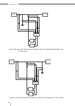
5.2.3 Electrical connection of an AHF single module
The electrical interfaces of the rack and wall modules are the same so only the electrical
connection of the rack module is described here.
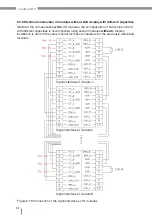
Components for the installation of AHF-LCD R 400 V 50 A single module:
• 3-phase alternating current power supply line
• 1 N-conductor,
• 1 PE conductor
• 1 external current transformer line
1S1
1S2
2S1
2S2
3S1
3S2
CT
A
A-N
B
B-N
C
C-N
B
C
N
PE
A
AHF
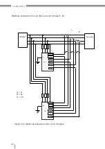
Figure 3-4c Electrical connection
of the AHF-LCD R 400 V 50 A AHF
(3-phase conductor system with N-conductor)
• Input A – phase L1 input terminal;
• Input B – phase L2 input terminal;
• Input C – phase L3 input terminal;
• N – neutral conductor terminal;
• PE ground wire
Note: Because the housing is made of metal, the terminal must be connected to ground.
Load side
Grid side
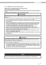
WARNING
Risk of injury due to electrical voltage!
Severe bodily injury or death can result
from:
• Touching bare or stripped leads that are energized.
• Inputs of the device and its components that pose a hazard when touched.
Therefore please abide by the following:
•
Switch off your installation before commencing work!
Check to be sure it is de-energized!
Ground the installation! Use the ground connection points with the ground sym-
bol to do so!


