Janitza AHF
30
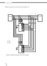
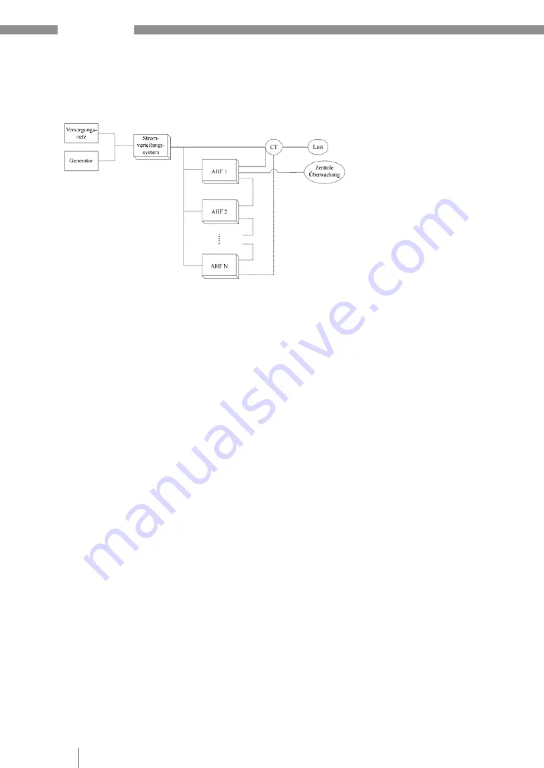
Figure 3-16 Electrical connection of
several modules without display (1~N)
5.4 Electrical connection of several modules without display
5.4.1 Electrical connection of the AHF R 400 V 50 A AHF
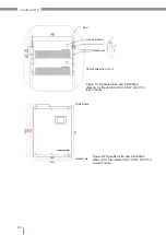
Module AHF R 400 V 50 A, for example, is intended for installation in switchboard cabinets
and can be monitored with a 7-inch monitor.
The device numbers of all modules are specified by means of a DIP switch on the back of
the housing.
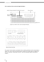
In contrast to modules with a display that have their own monitoring screen, there are vari-
ous different methods for connecting a signal interface for the modules without a display.
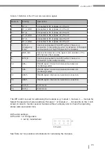
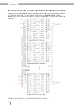
Connect the CT signal interface as well as 485+, 485-, EPO_A and GND_ISO.
Example: Three AHF R 400 V 50 A modules arranged in parallel
• Filter module 1: DIP switch to CT2=CT1=CT0=0
• Filter module 2: DIP switch to CT2=CT1=0, CT0=1
• Filter module 3: DIP switch to CT2= 0, CT=1 and CT0=0
For monitoring or troubleshooting, connect an external 7-inch monitor (available as an
option) to the monitoring interface of module 1.
The same principle can also be used for two, four, five or more modules arranged in
parallel. The combination of several devices mentioned above can be used for the
following modules:
• AHF R 400 V 25 A,
• AHF R 400 V 35 A,
• AHF R 400 V 50 A,
• AHF R 400 V 60 A
• AHF R 400 V 75 A,
• AHF R 400 V 100 A,
• AHF R 400 V 150 A


