Janitza AHF
59
1)
Only with the optional IO module
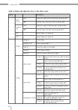
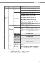
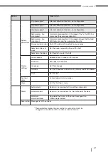
Menu
Description
Main menu
data
Power
Apparent power
Apparent power of phase A/B/C on the grid side
Apparent power of phase A/B/C on the load side
Active power
Active power of phase A/B/C on the grid side
Active power of phase A/B/C on the load side
Reactive power
Reactive power of phase A/B/C on the grid side
Reactive power of phase A/B/C on the load side
cos
φ
Cosine of the phase angle between the mains voltage
and the fundamental oscillation current
Cosine of the phase angle between the load voltage
and the fundamental oscillation current
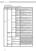
IO &
Temperature
1)
IO status
Inputs/outputs Status information on potential-free
contact
Temperature
1)
Nodes 1, 2, 3
Temperature display of the inverter
for phase A/B/C
Nodes 4, 5, 6
Local temperature of the inductance
assembly
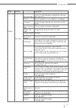
Test
Analog address 1
2)
Variable DSP address
Analog address 2
2)
Analog address 3
2)
Variable DSP address
Analog address 4
2)
Analog address 5
2)
Variable DSP address
Analog address 6
2)
Pos. bus voltage
2)
Calibration of DC voltage
Neg. bus voltage
2)
Version
Software version
no.
Version no.
System model
Displays the voltage level of the AHF, rated capacity and
3-phase 3-conductor system or 3-phase 4-conductor
system
2)
The parameters marked in gray are factory set and can only be
changed in consultation with a Janitza service technician

