www.janitza.de
65
Busbar tap-off unit
INFORMATION
The following steps show the assembly of the bus-
bar tap-off unit (system BD2 - 250/400/530 A vari-
ants, without cover disconnector), regardless of
the equipment/installation. Please note, as already
described under „Installation and equipment op-
tions – schematic diagrams“ on page 60, that the
equipment of your busbar tap-off unit and thus the
information on the mounting of components and ca-
bling may differ from the following figures!
The 250 A, 400 A and 530 A versions of the AKM
have
no
cover disconnector. The assembly and dis-
assembly of the busbar tap-off unit (AKM)
without
cover disconnector is only possible when the cover
is open.
A finger-safe design provides protection against
contact.
For the AKM versions with switching elements (fuse
switch or circuit breaker) the cover opens only when
the switching element is switched off (interlock)!
11.2 Busbar tap-off unit –
System BD2 - 250/400/530 A,
without cover disconnector
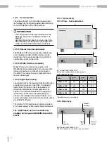
1. Use a hexagon socket wrench or other suitable
tool to open the busbar tap-off unit (AKM).
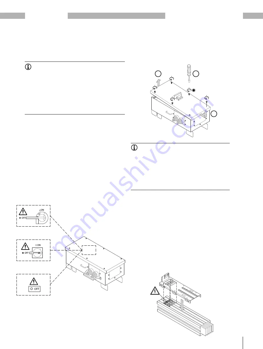
Fig. 1: AKM with switching elements
Safety load switch
(FS)
Circuit breaker,
rotary actuator (LSD)
Circuit breaker,
motor actuator (LSM)
Depending on the AKM:
4x or 6x 10 mm (8 Nm)
Fig. 2: Open the AKM (1, 2, 3)
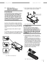
2. The 250/400/530 A versions of the AKM are
fixed to the busbar with a mounting aid that is
included.
Plug the mounting aid (anti-twist protection -
prevents incorrect positioning of the AKM) onto
the tap-off site of the busbar system. Please
note that depending on the national regulations
for electrical installations, mounting the tap-off
units while live might or might not be permit-
ted. In the case of live, switch off the voltage
and protect the busbar circuit against being
switched on again in accordance with local
regulations (see warning symbol).
INFORMATION
Check the required space before installing
the AKM. Tap-off units must not be placed at
connection points over terminal blocks! The space
requirements of the AKM must be taken into
account already during the project planning stage!
Please also observe the further assembly and
installation instructions of the busbar system
manufacturer.
Fig. 3: Attach the mounting aid
1
2
3


