background image

Busbar tap-off unit

www.janitza.de

52

10.  Product description

10.1  Product description and application 

areas

The busbar tap-off unit (AKM tap-off unit with 
measurement technology) is used for the analysis 
of energy efficiency in busbar trunking systems of 
the type BD2. The BD2 busbar trunking system is 
used for power transmission and distribution with 
communication capability in office buildings and 
industrial plants.

This supplementary user manual for the busbar 
tap-off unit assumes that a BD2 busbar system is 
already installed. Variants for other busbar sys-
tems must be evaluated in each individual case. 
The implementation depends on technical and 
economic boundary conditions.

The busbar tap-off unit for the BD2 busbar trunk-
ing system offers maximum safety through tested 
low-voltage switchgear combinations according to 
IEC 60439-1 / -21. 

The high short-circuit resistance and low fire load 
due to the sheet steel housing increase safety for 
people and buildings.

In contrast to conventional cable installation, 
where electricity can only be tapped at fixed 
points, the ready-dimensioned busbar tap-off units 
can be used flexibly and varied on the busbar 
trunking systems (BD2). The installation is carried 
out without any intervention in the connected 
consumer (e.g. machine) and the associated loss 
of warranty.

The AKM busbar tap-off unit 

 ·is a ready dimensioned system for the con-

nection and energy monitoring of an electrical 
consumer (e.g. a machine).

 ·performs a detailed energy efficiency analysis at 

the machine level.

 ·is a ready dimensioned system which monitors 

electrical parameters, such as currents, voltages, 
power, power quality, etc. via the built-in mea-
surement device and the associated network 
analysis

 ·can monitor the enclosure temperature and indi-

rectly the entire busbar system.

Various options and design variants of the bus-
bar tap-off unit allow adaptation to the respective 
measurement task. This includes, for example, an 
extended RCM measurement and the recording of 
additional consumption values via pulse inputs.

INFORMATION

Please note!

The size of the busbar tap-off unit depends on the 

variants (see „Technical data“ on page 72)! 

The feed of the 125 A version of the busbar tap-

off unit is equipped with a cover disconnector, 

which disconnects the tap-off unit from the live 

busbar system when the cover is opened. This 

allows shockproof working on the installed tap-

off unit.

With all other versions of the busbar tap-off 

unit, there is no disconnection when the cover 

is opened! In this case, a finger-safe design 

provides protection against contact.

Summary of Contents for AKM 96RM-E

Page 1: ... 6441 9642 22 E Mail info janitza de www janitza de www janitza de Stromschienen Abgangskasten für das Stromschienensystem BD2 Busbar tap off unit for the busbar system BD2 AKM 96RM E AKM 96 PA AKM 806 Ergänzendes Benutzerhandbuch Supplementary user manual Art Nr 33 03 519 E n g l i s h v e r s i o n f r o m p a g e 3 9 ...

Page 2: ...auf S 8 Produktbeschreibung auf S 14 Montage auf S 24 Installation auf S 32 Technische Daten auf S 34 Service und Wartung auf S 37 EN TABLE OF CONTENTS on page 42 Information on the product and the user manual on page 44 Safety on page 46 Product description on page 52 Mounting on page 62 Installation on page 70 Technical data on page 72 Service and maintenance on page 75 ...

Page 3: ...he Änderungen vorbehalten Die Inhalte unserer Dokumentation wurden mit größter Sorgfalt zusammengestellt und entsprechen unserem derzeitigen Informationsstand Dennoch weisen wir darauf hin dass die Aktualisierung dieses Dokuments nicht immer zeitgleich mit der technischen Weiterentwicklung unserer Produkte durchgeführt werden kann Informationen und Spezifikationen können jederzeit geändert werden ...

Page 4: ...tromschienen Abgangskasten ausgehende Gefahren 10 2 8 Sicherheitshinweise zum Umgang mit Stromwandlern und Messgeräten mit Differenzstrommessung 11 2 9 Umgang mit Batterien Akkumulatoren 12 3 Produktbeschreibung 14 3 1 Produktbeschreibung und Einsatzbereiche 14 3 2 Eingangskontrolle 15 3 3 Bestimmungsgemäße Verwendung 15 3 4 Leistungsmerkmale 16 3 5 EU Konformitätserklärung 16 3 6 Normen und Stand...

Page 5: ...des Geräts Typenschild 21 3 13 Installations und Bestückungsoptionen schematische Darstellungen 22 4 Montage 24 4 1 Stromschienen Abgangskasten System BD2 125 A mit Deckeltrenner 24 4 2 Stromschienen Abgangskasten System BD2 250 400 530 A ohne Deckeltrenner 27 5 Installation 32 5 1 Stromlaufplan Verdrahtungsvariante 32 6 Technische Daten 34 6 1 Technische Daten des Stromschienen Abgangskastens 34 ...

Page 6: ...che Änderungen Achten Sie darauf dass Ihr Produkt mit dem Be nutzerhandbuch übereinstimmt Dieses Benutzerhandbuch ist gültig für den Stromschienen Abgangskasten Gesonderte Gültigkeiten und Unterscheidungen sind gekenn zeichnet Lesen und verstehen Sie zunächst produktbe gleitende Dokumente auch zu den verbauten Geräten Modulen und Komponenten Halten Sie produktbegleitende Dokumente wäh rend der ges...

Page 7: ...t und Straße komplett mit Zubehör Beachten Sie gesonderte Bestimmungen für Geräte mit verbauten Batterien oder Akkus Geräte Module und Komponenten nicht eigen ständig öffnen oder reparieren da ansonsten der Anspruch auf Gewährleistung erlischt Für die Entsorgung des Produkts Geräts der Komponenten oder der Module beachten Sie bitte nationale Bestimmungen Entsorgen Sie gegebe nenfalls einzelne Teil...

Page 8: ...auf mög liche Verletzungsgefahren aufmerksam Beachten Sie alle unter diesem Symbol aufgeführten Hinwei se um mögliche Verletzungen oder gar Todesfälle zu vermeiden 2 2 Gefahrenstufen Warn und Sicherheitshinweise sind durch ein Warnsymbol hervorgehoben und die Gefahren stufen sind je nach Gefährdungsgrad wie folgt dargestellt GEFAHR Warnt vor einer unmittelbar drohenden Gefahr die bei Nichtbeachtun...

Page 9: ...d der Technik und den anerkannten sicherheitstechnischen Re geln trotzdem können Gefahren entstehen Beachten Sie Sicherheitsvorschriften und Warn hinweise Sollten Sie den Hinweisen nicht folgen kann dies Personenschäden und oder Schäden am Produkt hervorrufen Jegliche unerlaubte Manipulation oder Verwen dung dieses Produkts die über die angegebenen mechanischen elek trischen oder anderweitigen Bet...

Page 10: ...Personal an Geräten Modulen Komponen ten Baugruppen Systemen und Stromkrei sen arbeiten Verwenden Sie Ihr Gerät Modul Komponen te stets so wie in den zugehörigen Nut zungsinformationen beschrieben Senden Sie bei erkennbaren Beschädigungen das Gerät Modul Komponente zurück an den Hersteller 2 6 Gewährleistung bei Schäden Jegliche unerlaubte Manipulation des Produkts Geräte Module Komponenten begrün...

Page 11: ...ie ausschließlich der Überwachung von Differenzströmen oder der Ausfallüberwachung dienen Die Verwendung der Warnimpulse als eigenständige Schutzeinrichtung gegen elektrische Schläge kann zu Verletzungen bis zum Tod führen Verwenden Sie Geräte mit Differenzstrom messung nicht als eigenständige Schutzein richtung Wählen Sie geeignete Schutzein richtungen für Ihre Anlage VORSICHT Verletzungsgefahr o...

Page 12: ...leiche oder von Janit za empfohlene Typen ersetzen Beim Einbau der Batterie die Polarität be achten Batterien nur mit nicht leitenden Werkzeugen z B Pinzetten aus Kunststoff entnehmen Batterien nicht wieder aufladen nicht zerle gen nicht über 100 C 212 F aufheizen oder verbrennen Batterien nicht mit dem Hausmüll entsorgen Entsorgungsvorschriften in der jeweiligen Geräte Dokumentation beachten Batt...

Page 13: ...www janitza de 13 Stromschienen Abgangskasten ...

Page 14: ...ation verläuft ohne Ein griff in den angeschlossenen Verbraucher z B Maschine und den damit verbundenen Gewähr leistungsverlust Der Stromschienen Abgangskasten AKM ist ein fertig dimensioniertes System zum An schluss und der energetischen Überwachung eines elektrischen Verbrauchers z B einer Maschine übernimmt eine detaillierte Analyse der Energie effizienz auf Maschinenebene als fertig dimensioni...

Page 15: ...ahrloser Be trieb des Produkts nicht mehr möglich ist trennen Sie das Produkt unverzüglich vom Be trieb sichern Sie das Produkt gegen wiedereinschal ten Es ist anzunehmen dass ein gefahrloser Betrieb nicht mehr möglich ist wenn das Produkt z B eine sichtbare Beschädigung aufweist trotz intakter Netzversorgung nicht mehr arbeitet längere Zeit ungünstigen Verhältnissen z B Lagerung außerhalb der zul...

Page 16: ... über versilberte Lyra Kontakte Weitere Merkmale des Stromschienen Abgangs kastens mit Komponenten und des Stromschie nensystems BD2 entnehmen Sie entsprechend Ihrer Ausführung den Nutzungsinformationen der Hersteller Für weitere Informationen zu den verbauten Komponenten wenden Sie sich an die Janitza electronics GmbH 3 5 EU Konformitätserklärung Die von der Janitza electronics GmbH angewende ten...

Page 17: ...B B zusätzlich das Messgerät RCM 202 AB 2 Der AKM benötigt zur Erfassung externer Impulse ein Netzteil 24 V zur Versorgung des Impulsgebers AKM 96 PA Stromschienen Abgangskasten mit Messgerät UMG 96 PA AKM 96 PA 125 AKM 96 PA 250 AKM 96 PA 400 AKM 96 PA 530 Maximaler Abgangs strom 125 A 250 A 400 A 530 A Stromwandler 150 A 5 A Kl 1 250 A 5 A Kl 1 400 A 5 A Kl 1 600 A 5 A Kl 1 Strommessung 3P N Eth...

Page 18: ... Variante des Strom schienen Abgangskasten ist mit einem Deckel trenner versehen der bei einer Deckelöffnung den Abgangskasten vom unter Spannung stehenden Stromschienen System trennt Dies erlaubt ein berührungssicheres Arbeiten am montierten Ab gangskasten Bei allen anderen Varianten des Stromschienen Ab gangskastens erfolgt bei einer Deckelöffnung keine Trennung Hierbei erfüllt ein fingersichere...

Page 19: ...terten Differenzstrommessung RCMplus nach Typ A B B durch verbaute Differenzstrom Messgeräte RCM 202 AB 3 9 5 Temperaturmessung Die Innenraum Temperatur des Stromschienen Abgangskastens misst ein PT100 Temperatur fühler Der PT100 Temperaturfühler ist in der Nähe der NH Sicherungen verbaut wo die größte Erwärmung des AKMs zu erwarten ist 3 9 6 Leistungseingang Deckeltrenner und Berührschutz Das Sch...

Page 20: ...n Sie in den Nutzungsinformationen zu den verbauten Messgeräten 3 11 1 Ethernet Schnittstelle Standard Die Modbus TCP IP Kommunikation erfolgt über eine industriegerechte RJ45 Schnittstelle die vom Messgerät zu einer RJ45 Anschlussbuchse am AKM führt 3 11 2 RS485 Schnittstelle Standard Die Modus RTU Kommunikation erfolgt über 2 RS485 Schnittstellen die von den Anschlüssen des Messgeräts zu einer B...

Page 21: ...kelnummer des Herstellers 6 Data Matrix Code Inhalt verschlüsselte Artikelnummer und Typenbezeichnung 7 Hersteller Logo Logo des Geräte Herstellers 8 Gerätetyp AKM Typ 9 Herstell Monat Jahr Hardware Index Datum der Geräte Herstellung und Hardware Version des Geräts 10 CE Kennzeichnung Siehe Kap EU Konformitätserklärung und Normen und Standards auf S 16 11 Seriennummer Nummer zur Identifikation des...

Page 22: ...us der Halterung herausgezogen und um 180 gedreht eingesteckt werden N L1 L2 L3 PE N L INFORMATION Die schematischen Darstellungen der Installationen zeigen Beispiele Die tatsächliche Installation Bestü ckung ist abhängig von der gewählten Stromschie nen Abgangskasten Variante Abb Variante 1 AKM 96RM E 125 mit Lage des PE Anschlusses unten Kasten wird im Auslieferzustand montiert ...

Page 23: ...hutzerdung Schutzleiter 10 Kabel mit Verschraubung Leistungsausgang zum Betriebsmittel 11 Absicherung Sicherungsunterteil 3x NH Sicherung siehe Kap Technische Daten 12 Durchgangsklemme blau Erdungsklemme grün gelb 13 Stromwandler 4x je nach Option 14 Differenzstromwandler 1x Option 15 Deckeltrenner Buchse Nur bei der 125 A Variante des Stromschienen Abgangskastens vorhanden 16 Stromschienen Abgang...

Page 24: ...Deckeltrenner der bei einer Deckelöffnung den Abgangskasten vom unter Spannung stehen den Stromschienen System trennt Dies erlaubt ein berührungssicheres Arbeiten am montier ten Abgangskasten Alle anderen Varianten des Stromschienen Abgangskastens besitzen keinen Deckeltrenner Hierbei erfüllt ein finger sicherer Aufbau den Berührschutz Sichern Sie den geöffneten AKM gegen Wie dereinschalten verhin...

Page 25: ...werden Deshalb empfehlen wir sichten Sie die örtlichen Gegebenheiten durch Ins tallationsfachpersonal 5 Montieren und installieren Sie Ihr Kabel zum Verbraucher zum Betriebsmittel wie in der Abbildung 5 dargestellt Beachten Sie diese Abbildung dient ausschließlich der Montage und Installation des Abgangskabels der einzel nen Phasen des Neutralleiters und des Schutz leiters und entspricht nicht dem...

Page 26: ... AKMs 7 Entfernen Sie für die 125 A Variante des AKMs das Vorhängeschloss zur Sicherung gegen un vorhergesehenes Schließen des AKMs Beachten Sie auch hierbei dass je nach Lan desvorschrift für Elektroinstallationen die Ab gangskästen unter Spannung stehen könnten 8 Schalten Sie die Energiezufuhr Spannung des Stromschienen Strangs Ihres Systems ein und setzen damit Ihren AKM und die anhängenden Ver...

Page 27: ...es Stromschie nen Abgangskasten AKM einen Sechskant Steckschlüssel oder ein anderes geeignetes Werkzeug Abb 1 AKM mit Schaltelementen Sicherheitslastschalter FS Leistungsschalter Drehantrieb LSD Leistungsschalter Motorantrieb LSM je nach AKM 4x oder 6x 10 mm 8 Nm Abb 2 AKM öffnen 1 2 3 2 Bei den 250 400 530 A Varianten des AKMs erfolgt die Befestigung an der Stromschiene mit einer mitgelieferten A...

Page 28: ...tieren Sie den AKM an den Haltebolzen der Aufsetzhilfe siehe Abb 6 Beachten Sie auch hier können je nach Landesvorschrift die Abgangsstellen der Stromschienen unter Spannung stehen siehe Warnsymbol Abb 6 AKM justieren 1 2 6 Abb 7 Kipphebel umlegen AKM einrasten 3 Führen Sie den AKM mit offenem Kipphebel in die Halteöffnung der Aufsetzhilfe 4 Schieben Sie die Kontakte des AKMs in die Abgangsstelle ...

Page 29: ...Stromschienen unter Spannung stehen siehe Warnsymbol Abb 8 Offener AKM 8 Montieren und installieren Sie Ihre Kabel zu den Verbrauchern Betriebsmitteln wie in den folgenden Abbildungen dargestellt Die tatsäch lichen Darstellungen des AKMs und des Kabel abgangs können abweichen Abb 9 Kabel Einführung öffnen 4x 10 mm Abb 10 Kabel Einführung mit Kabeltüllen Zugentlastung integriert demontieren Abb 11 ...

Page 30: ...Sie bei der Montage und Installation von Kabeln und Leitungen Herstellerangaben zu Biegeradien von Kabel und Leitungen Halten Sie Luft und Kriechstrecken an den An schlussstellen ein Treffen Sie ggf zusätzliche Maßnahmen wie Phasentrennwände und Iso lation von Kabelschuhen M8 15 Nm M10 25 Nm INFORMATION Eine Variante eines Stromlauf Verdrahtungsplans für den AKM finden Sie im Kap Stromlaufplan Ver...

Page 31: ...cherungen in die dafür vorgesehenen Sicherungssockel Ver wenden Sie zum Einsetzen einen passenden NH Sicherungshandschuh 12 Schalten Sie die Energiezufuhr Spannung des Stromschienen Strangs Ihres Systems ein und setzen damit Ihren AKM und die anhängenden Verbraucher in Betrieb ...

Page 32: ...30 DI S1 S2 S1 S2 S1 S2 S1 S2 230VAC 24VDC RJ45 Modbus stecker Modbusbuchse Power Buchse Signal X2 M8 3pol 24V X0 X3 M12 4pol A codiert X4 M12 4pol A codiert Modbus Leitung verdrillt nicht belegt X5 RJ45 LAN Modbus Leitung verdrillt 5 1 Stromlaufplan Verdrahtungsvariante Der folgende Stromlaufplan zeigt eine Ver drahtungsvariante des Stromschienen Abgangs kastens AKM Die Verdrahtung ist abhängig v...

Page 33: ...www janitza de 33 Stromschienen Abgangskasten ...

Page 34: ...ung gesamt 97 W Lüftung keine Fremdlüftung erforderlich Mechanischer Aufbau Länge x Breite x Höhe siehe Tabelle Maße auf S 20 Leistungsabgang Spannung Typ AKM 96RM E max 277 V 480 V 10 Typ AKM 96 PA max 277 V 480 V 10 Typ AKM 806 max 230 V 400 V 10 Maximal zulässiger Strom abhängig vom Gerätetyp max 125 A 250 A 400 A 530 A Belastungsfaktor Dauer 24 h 0 6 Belastungsfaktor Kurzzeit 2 h 1 0 Absicheru...

Page 35: ...rer Nähe zur NH Sicherung Ethernet Schnittstelle Anschluss Han PushPull RJ45 Protokolle AKM 96RM E TCP IP DHCP Client BootP Modbus TCP Port 502 ICMP Ping NTP Modbus RTU over Ethernet FTP SNMP AKM 96 PA TCP IP DHCP Client BootP Modbus TCP Port 502 ICMP Ping NTP AKM 806 Modbus TCP DHCP Client SNMP V2c Serielle Schnittstelle RS485 Modbus RTU Slave 9 6 19 2 38 4 57 6 115 2 kbps Anschluss M12 4polig A ...

Page 36: ... geräte und Komponenten Die Varianten der Stromschienen Abgangskästen sind vielfältig und mit unterschiedlichen Bestü ckungen und Installationen zu erwerben Deshalb beachten Sie die technischen Daten in allen Nutzungsinformationen die zu den verbauten Messgeräten und Komponenten gehören ...

Page 37: ...ce und Wartungsarbeiten Ihre Anlage und den Stromschienen Abgangskasten spannungs frei schalten gegen Wiedereinschalten sichern Spannungsfreiheit feststellen Erden und Kurz schließen benachbarte unter Spannung stehen de Teile abdecken oder abschranken Nur Elektrofachkräfte und elektrotechnisch qualifiziertes Personal dürfen die im Folgenden beschriebenen Arbeiten ausführen IEC 61439 1 EN 50110 1 H...

Page 38: ...Änderungen vorbehalten Den aktuellen Status des Dokuments finden Sie im Download Bereich auf www janitza de Janitza electronics GmbH Vor dem Polstück 6 D 35633 Lahnau Support Tel 49 6441 9642 22 E Mail info janitza de info janitza de www janitza de ...

Page 39: ...ectronics GmbH Vor dem Polstück 6 D 35633 Lahnau Support tel 49 6441 9642 22 Email info janitza de www janitza de www janitza de Busbar tap off unit for the busbar system BD2 AKM 96RM E AKM 96 PA AKM 806 Supplementary user manual Art Nr 33 03 519 ...

Page 40: ...it www janitza de 40 Busbar tap off unit for the busbar system BD2 AKM 96RM E AKM 96 PA AKM 806 Supplementary user manual Doc no 2 551 030 0 i Date 12 2020 The German version is the original edition of the documentation ...

Page 41: ...the current state of the information available to us Nonetheless we wish to point out that updates of this document are not always possible at the same time as technical refinements are implemented in our products Please see our website under www janitza de for the current version Please see our website under www janitza de for the current version ...

Page 42: ... 48 2 8 Safety information for handling current transformers and measurement devices with residual current measurement 49 2 9 Handling batteries accumulators 50 3 Product description 52 3 1 Product description and application areas 52 3 2 Incoming goods inspection 53 3 3 Intended use 53 3 4 Performance characteristics 54 3 5 EU conformity declaration 54 3 6 Norms and standards 54 3 7 Types variant...

Page 43: ...device rating plate 59 3 13 Installation and equipment options schematic diagrams 60 4 Mounting 62 4 1 Busbar tap off unit System BD2 125 A with cover disconnector 62 4 2 Busbar tap off unit System BD2 250 400 530 A without cover disconnector 65 5 Installation 70 5 1 Circuit diagram wiring variant 70 6 Technical data 72 6 1 Technical data of the busbar tap off unit 72 6 2 Technical data of the ins...

Page 44: ...hese rights 8 3 Technical changes Make sure that your product matches the user manual This user manual applies to the busbar tap off unit Separate validities and distinctions are marked First read and understand the documents associ ated with the product including those relating to the installed devices modules and components Keep the documents associated with the product available for the entire ...

Page 45: ...road freight complete with accessories Observe special regulations for devices with built in batteries or rechargeable batteries Do not open or repair devices modules and com ponents on your own otherwise the warranty will become void For the disposal of the product device compo nents or modules please observe national regu lations Dispose of individual parts as applicable depending on their compo...

Page 46: ...is general warning symbol draws attention to a possible risk of injury Be certain to observe all of the information listed under this symbol in order to avoid possible injury or even death 9 2 Hazard levels Warning and safety information is marked by a warning symbol and the hazard levels are shown as follows depending on the degree of hazard DANGER Warns of an imminent danger which if not avoided...

Page 47: ...s modules and components 9 3 Product safety The product reflects current engineering practice and accepted safety standards but hazards can arise nonetheless Observe the safety regulations and warning no tices If notices are disregarded this can lead to personal injury and or damage to the product Every type of tampering with or use of this prod uct which goes beyond the mechanical electrical or o...

Page 48: ...ing death Only electrically qualified personnel are per mitted to work on the devices components assemblies systems and current circuits Always use your device module component as described in the associated usage infor mation If there is discernible damage send the de vice module component back to the manu facturer 9 6 Warranty in the event of damage Any unauthorized manipulation of the product d...

Page 49: ...ement can trig ger warning pulses if limit values are exceeded and these are used exclusively for monitoring residual currents or failure monitoring Use of the warning pulses as a stand alone protective device against electrical shock can lead to injury and even death Do not use devices with residual current mea surement as a stand alone protective device Employ suitable protective devices for you...

Page 50: ...ttery with the same type or types recommended by Janitza Observe the polarity when installing the battery Remove batteries only with non conductive tools e g plastic tweezers Do not recharge disassemble burn or heat batteries above 100 C 212 F Do not dispose of batteries with household waste Follow the disposal instructions in the respective device documentation Keep batteries away from children a...

Page 51: ...www janitza de 51 Busbar tap off unit ...

Page 52: ... The installation is carried out without any intervention in the connected consumer e g machine and the associated loss of warranty The AKM busbar tap off unit is a ready dimensioned system for the con nection and energy monitoring of an electrical consumer e g a machine performs a detailed energy efficiency analysis at the machine level is a ready dimensioned system which monitors electrical para...

Page 53: ...is no longer possible Disconnect the product from operation immedi ately Secure the product against being switched on again It can be assumed that safe operation is no longer possible for example if the device Has visible damage No longer functions despite an intact power supply Was subjected to extended periods of unfavor able conditions e g storage outside of the per missible climate thresholds ...

Page 54: ...tapping via silver plated contacts For further characteristics of the busbar tap off unit with components and the BD2 busbar system please refer to the manufacturer s usage informa tion for your version For further information on the installed components please contact Janitza electronics GmbH 10 5 EU conformity declaration Please see the EU declaration of conformity post ed at www janitza de for ...

Page 55: ... the RCM 202 AB measurement device 2 To record external pulses the AKM requires a power supply unit 24 V to supply the pulse generator AKM 96 PA Busbar tap off unit with UMG 96 PA measurement device AKM 96 PA 125 AKM 96 PA 250 AKM 96 PA 400 AKM 96 PA 530 Maximum output current 125 A 250 A 400 A 530 A Current transformer 150 A 5 A Cl 1 250 A 5 A Cl 1 400 A 5 A Cl 1 600 A 5 A Cl 1 Current measuremen...

Page 56: ...connector which disconnects the tap off unit from the live busbar system when the cover is opened This allows shockproof working on the installed tap off unit With all other versions of the busbar tap off unit there is no disconnection when the cover is opened In this case a finger safe design of the busbar tap off unit provides protection against contact AKM 806 Busbar tap off unit with UMG 806 m...

Page 57: ...r the AKMs 250 400 530 A there is the op tion for enhanced residual current measurement RCMplus according to Type A B B by means of built in RCM 202 AB residual current measurement devices 10 9 5 Temperature measurement The interior temperature of the busbar tap off unit is measured by a PT100 temperature sensor The PT100 temperature sensor is installed close to the NH fuses where the greatest hea...

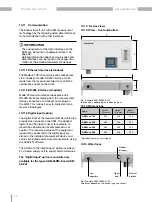
Page 58: ...on of the installed measurement devices 10 11 1Ethernet interface standard The Modbus TCP IP communication takes place via an industry standard RJ45 interface which leads from the measurement device to an RJ45 connection socket on the AKM 10 11 2RS 485 interface standard Mode RTU communication takes place via 2 RS 485 interfaces leading from the measurement device connections to a socket and a plu...

Page 59: ... part number 6 Data matrix code Content coded part number and type designation 7 Manufacturer s logo Logo of the device manufacturer 8 Device type AKM type 9 Month year of manufacture hard ware index Date of device manufacture and hardware version of the device 10 CE conformity marking See chapter EU conformity declaration and Norms and standards on page 54 11 Serial number Number for identificati...

Page 60: ...evice can be pulled out of the hold er rotated by 180 and reinserted N L1 L2 L3 PE N L INFORMATION The schematic representations of the installations show examples The actual installation equipment depends on the busbar tap off unit variant selected Fig Variant 1 AKM 96RM E 125 with PE connection below The enclosure is mounted in the as delivered condition ...

Page 61: ...p off unit 9 Protective earth protective conductor 10 Cable with screw connection Power output to the equipment 11 Fuse fuse base 3x NH fuses see chapter Technical data 12 Through terminal blue Ground terminal green yellow 13 Current transformer 4x depending on option 14 Residual current transformer 1x option 15 Cover disconnector socket Only available for the 125 A version of the busbar tap off u...

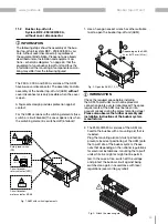
Page 62: ...om the live busbar system when the cover is opened This allows shockproof working on the installed tap off unit All other versions of the busbar tap off unit do not have a cover disconnector In this case a finger safe design provides protection against contact Secure the open AKM against being switched on again use a padlock for example to pre vent the AKM from closing 3 Connect the AKM to the tap...

Page 63: ...mend that you have the local conditions checked by qualified installation personnel 5 Mount and install your cable to the consumer equipment as shown in figure 5 Please note that this illustration is only for the assembly and installation of the outgoing cable the individual phases the neutral conductor and the protec tive conductor and does not correspond to the actual assembled AKM Fig 5 Assembl...

Page 64: ...he AKM only 7 For the 125 A version of the AKM remove the padlock used to prevent the AKM from closing unexpectedly Again note that depending on the country s electrical installation regulations the tap off units may be live 8 Switch on the power supply voltage of the busbar system of your system and thus put your AKM and the attached consumers into operation ...

Page 65: ...wrench or other suitable tool to open the busbar tap off unit AKM Fig 1 AKM with switching elements Safety load switch FS Circuit breaker rotary actuator LSD Circuit breaker motor actuator LSM Depending on the AKM 4x or 6x 10 mm 8 Nm Fig 2 Open the AKM 1 2 3 2 The 250 400 530 A versions of the AKM are fixed to the busbar with a mounting aid that is included Plug the mounting aid anti twist protect...

Page 66: ...KM using the fixing bolts of the mounting aid see Fig 6 Please note that here too depending on the national regulations the tap off sites of the busbars may be live see warning symbol Fig 6 Adjusting the AKM 1 2 6 Fig 7 Flip the lever engage the AKM 3 With the lever open guide the AKM into the bracket opening of the mounting aid 4 Push the contacts of the AKM into the tap off site of the busbar an...

Page 67: ... off sites of the busbars may be live see warning symbol Fig 8 AKM open 8 Assemble and install your cables to the con sumers operating equipment as shown in the following figures The illustrations of the actual AKM and the cable outlet may differ Fig 9 Opening the cable inlet 4x 10 mm Fig 10 Removing the cable inlet with cable grommets strain relief integrated Fig 11 Mounting the cable holder 2x 1...

Page 68: ...unting and installing cables and lines Manufacturer s information on bending radii of cables and wires Maintain clearance and creepage distances at the connection points If necessary take addi tional measures such as phase separators and insulation of cable lugs M8 15 Nm M10 25 Nm INFORMATION A variant of a circuit diagram wiring diagram for the AKM can be found in chapter Circuit diagram wiring v...

Page 69: ... 11 Insert suitable NH fuses in the fuse sockets provided Use a suitable NH fuse glove for insertion 12 Switch on the power supply voltage of the busbar system of your system and thus put your AKM and the attached consumers into operation ...

Page 70: ...34 1 2 I5 I6 28 29 30 DI S1 S2 S1 S2 S1 S2 S1 S2 230VAC 24V DC RJ45 Modbus plug Modbus socket power Socket signal X2 M8 3pol 24V X0 X3 M12 4pol A coded X4 M12 4pol A coded Mobus cable twisted No connection X5 RJ45 LAN Mobus cable twisted 12 1 Circuit diagram wiring variant The following circuit diagram shows a wiring vari ant of the AKM busbar tap off unit The wiring depends on the selected AKM va...

Page 71: ...www janitza de 71 Busbar tap off unit ...

Page 72: ...ation No forced ventilation required Mechanical structure length x width x height See table Dimensions on page 58 Outgoing power feeder Voltage Type AKM 96RM E max 277 V 480 V 10 Type AKM 96 PA max 277 V 480 V 10 Type AKM 806 max 230 V 400 V 10 Maximum permissible current depending on the device type Max 125 A 250 A 400 A 530 A Load factor continuous 24 h 0 6 Load factor short term 2 h 1 0 Fuse pr...

Page 73: ...he NH fuse Ethernet interface Connection Han PushPull RJ45 Protocols AKM 96RM E TCP IP DHCP client BootP Modbus TCP port 502 ICMP ping NTP Modbus RTU over Ethernet FTP SNMP AKM 96 PA TCP IP DHCP client BootP Modbus TCP port 502 ICMP ping NTP AKM 806 Modbus TCP DHCP client SNMP V2c Serial interface RS 485 Modbus RTU Slave 9 6 19 2 38 4 57 6 115 2 kbps Connection M12 4 pin A coded 1x each socket and...

Page 74: ... devices and components There are many variants of the busbar tap off units and they can be purchased with different items of equipment and installations Consequently please note the technical data in all usage information which belongs to the in stalled measurement devices and components ...

Page 75: ...tages Before starting work also service and mainte nance work disconnect your system and the busbar tap off unit from the power supply se cure against reconnection verify that the system is voltage free ground and short circuit cover or block off adjacent live parts Only qualified electricians and personnel qual ified in electrical engineering may perform the work described below IEC 61439 1 EN 50...

Page 76: ... technical changes The current version of the document can be found in the download area at www janitza de Janitza electronics GmbH Vor dem Polstück 6 D 35633 Lahnau Support tel 49 6441 9642 22 Email info janitza de info janitza de www janitza de ...

Reviews: