background image

33

GridVis

®

 Collector

www.janitza.de

www.janitza.de

GridVis

®

 Collector

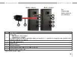
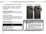
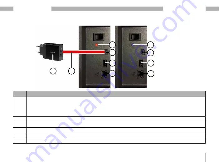
Fig.: 
Power supply, 
display elements 
and interfaces

Item Designation

1

Status LED

 · Blue: Battery fully charged.

 · Red:Battery is charging.

For additional LED statuses (operating modes), see section „4. 1 Location of connections and controls on the 

GridVis® Collector“ on page 26.

2

Mini-USB charging port

3

USB 2.0 port

4

Ethernet interface

5

USB charging cable (USB to mini-USB connector)

6

Charger (power supply unit)

Table: Battery power supply

Battery charged

2

5

6

2

1

3

3

4

4

Battery charging

1

Summary of Contents for GridVis Collector

Page 1: ...ectronics GmbH Vor dem Polst ck 6 D 35633 Lahnau Support Tel 49 6441 9642 22 Fax 49 6441 9642 30 Email info janitza de http www janitza de Mobile energy data collector GridVis Collector User Manual fi...

Page 2: ...ata collector Doc no 2 099 006 1 f Date 05 2023 Valid as of firmware 2 0 0 The German version is the original version of the documentation NOTE Please note that certain functions of the GridVis Collec...

Page 3: ...d reflect the current state of information available to us Nonethe less we would like to point out that updates of this document are not always possible at the same time as technical refinements are i...

Page 4: ...7 Performance characteristics 15 2 8 Identification of the device rating plate 16 3 Safety 18 3 1 Display of warning notices and safety information 18 3 2 Hazard levels 18 3 3 Product safety 19 3 4 Fu...

Page 5: ...es from RS 485 measurement devices 82 7 3 Synchronizing measured values with the GridVis software database 84 7 4 Integrating plug ins in the GridVis system service 88 7 5 Configuration of the automat...

Page 6: ...rising from them are the property of the respective owners of these rights 1 3 Technical changes Make sure that your device matches the user manual First read and understand the documents accom panyin...

Page 7: ...tronics GmbH We will promptly send you a special box for dangerous goods and the corresponding warning labels for identification Return the device with a damaged battery complete with carrying case an...

Page 8: ...t description No specialized knowledge of the GridVis network visu alization software is needed to operate the mobile Grid Vis Collector on site An intuitive capacitive 7 multi touch colour display wi...

Page 9: ...ster slave topology you can read out these devices using the UMG 604 UMG 605 UMG 508 UMG 509 UMG 511 UMG 512 or UMG 96 RM E mas ter devices and the respective PRO devices NOTE The GridVis Collector do...

Page 10: ...in good time and regularly NOTE Only configure one GridVis project per GridVis Collec tor The GridVis Collector has An internal UN38 3 certified lithium ion battery rechargeable battery with a runtim...

Page 11: ...uthentication As of firmware 2 0 0 the communication between the GridVis Collector and the PC server with installed GridVis software can be encrypted optionally Authentication and encryption are done...

Page 12: ...12 GridVis Collector www janitza de 2 1 3 5 6 7 4 2 4 Scope of delivery Fig GridVis Collector scope of delivery...

Page 13: ...data collector GridVis Collector 3 34 02 001 USB charger power supply input 100 240 V 50 60 Hz 0 7 A output 5 VDC 2 4 A 4 08 02 445 USB charging cable USB to mini USB connector 5 08 01 505 Ethernet c...

Page 14: ...aintenance Observe the safety information and technical specifica tions for the device with integrated rechargeable battery charger presented here in the user manual and in the enclosed documents 2 6...

Page 15: ...port Authentication PEAP with MSCHAPv2 TLS TTLS Encrypted communication via RSA keys between the GridVis Collector and the GridVis PC server Readout of devices with RS 485 interfaces via USB RS 485 co...

Page 16: ...16 GridVis Collector www janitza de 2 8 Identification of the device rating plate 5 1 2 4 3 6 7 8 9 10 11 Fig Rating plate...

Page 17: ...d in the documents to avoid possible injury or even death 3 Operating data Supply voltage and current 4 Device type Device designation 5 QR code Coded manufacturer data 6 Manufacturer s logo Logo of t...

Page 18: ...disregarded can result in property damage or environ mental damage 3 Safety The Safety section contains information which must be observed to ensure your personal safety and avoid material damage 3 1...

Page 19: ...nance Do not try to change the lithium ion battery of the device on your own Send defective devices back to the manufacturer complete and in the carrying case and observe the transport conditions 3 4...

Page 20: ...s acids alkalis gases vapours dust and radiation This can lead to a chemical reaction and to a defect of the device material damage or even personal injury in case of fire or explosion Protect the dev...

Page 21: ...not allow the device to charge while unattended Only use chargers authorized by the manufacturer for charging After charging disconnect your USB charger from the mains WARNING Warning against misuse o...

Page 22: ...of the device in microwave ovens or in areas exposed to electromagnetic radiation High frequency electromagnetic fields can damage the device Use your device only in permitted areas Please observe th...

Page 23: ...ttery Clean the housing the display and accessories especially the power supply unit of the GridVis Collector only with a dry microfibre cloth If the housing or accessories are very dirty use a microf...

Page 24: ...is not operated in accordance with the documentation protection is not ensured and dama ge to property or injury or even death may occur Any unauthorized manipulation or use of the device beyond the...

Page 25: ...25 www janitza de GridVis Collector...

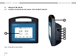
Page 26: ...26 GridVis Collector www janitza de 4 1 Location of connections and controls on the GridVis Collector 4 Design of the device 1 2 4 5 3 6 7 Fig Connections and controls...

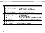
Page 27: ...e manufacturer 4 Status LED Display of the operating modes Green device in operation Blue device in charging state battery is full Red device in charge state Orange device is shutting down Yellow char...

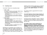
Page 28: ...stant surfaces Do not allow the device to charge while unattended Only use chargers authorized by the manufacturer for charging After charging disconnect your USB charger from the mains 4 2 Housing of...

Page 29: ...29 www janitza de GridVis Collector 270 mm 247 mm 91 mm Fig Housing of the GridVis Collector...

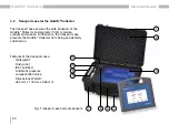
Page 30: ...nd protects it from moisture sunlight and shocks Furthermore the transport case prevents the GridVis Collector from being accidentally switched on Features of the transport case Waterproof Dust proof...

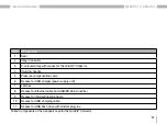
Page 31: ...Carrying handle 5 Pressure compensation valve 6 Recess for USB charger power supply unit 7 Latches 8 Recess for Ethernet cable and USB RS 485 converter 9 Recess for informational products 10 Recess f...

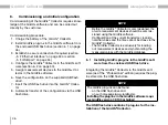
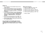
Page 32: ...Vis Collector on page 26 NOTE An internal charge controller automatically ends the charging process once the battery is fully charged Recommendation Observe the charging process and disconnect the ch...

Page 33: ...charging For additional LED statuses operating modes see section 4 1 Location of connections and controls on the GridVis Collector on page 26 2 Mini USB charging port 3 USB 2 0 port 4 Ethernet interfa...

Page 34: ...ector has a USB 2 0 port see figure on Fig Power supply display elements and interfaces on page 33 item 3 The USB 2 0 port is used to transfer parameters when the GridVis Collector is first commission...

Page 35: ...ission errors Also connect a termination resistor 120 part no 52 00 008 between terminals A and B of the RS 485 interface of your measurement device using the USB RS 485 converter cable Connect your U...

Page 36: ...n To perform a hardware reset hold down the push but ton item 1 for 10 seconds NOTE Use the Hardware reset only in exceptional cases e g if the GridVis Collector does not Shut down and switch off Resp...

Page 37: ...37 www janitza de GridVis Collector...

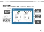
Page 38: ...than in the company network see Fig Example The IP addresses of the measurement devices are configured during initial setup via the GridVis software plug in or directly on the GridVis Collector in the...

Page 39: ...Transformer station 3 UMG 1 IP 192 168 5 201 Example Connection of the GridVis Collector to a company network via the IP address 10 10 10 12 and reading out on site with the IP address 192 168 5 200...

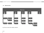
Page 40: ...enu Info LCD Time zone Language Setup Start Server mode Upload Download Device list Device mode Log Update Reset System Delete records Factory setting Ethernet WLAN Server Network 5 6 Menu structure F...

Page 41: ...41 www janitza de GridVis Collector...

Page 42: ...42 GridVis Collector www janitza de 9 10 11 12 13 14 5 7 Start screen 1 2 3 4 5 8 6 7 Fig Start screen...

Page 43: ...current date and time of the GridVis Collector 4 Display Storage capacity for measured values 100 corresponds to 60 GByte of free memory Synchronize the GridVis Collector with the GridVis database at...

Page 44: ...e operating mode Device mode Item Symbol Main menu functions Description The symbol of the activated function is shown in blue 10 Start button Opens the start screen Selection of the operating mode 11...

Page 45: ...45 www janitza de GridVis Collector...

Page 46: ...iguration via the USB flash drive NOTE Before the GridVis Collector is commissioned the on site measurement devices should be commis sioned using the GridVis software Configuration of the current tran...

Page 47: ...atic data reception Collector Receiver via a system service 4 Secure communication between the GridVis Col lector and the GridVis software using an RSA key 5 Data exchange between the plug ins interna...

Page 48: ...flash drive and click Open Your plug in now appears on the Downloaded tab Select the checkbox of your plug in and click the Install button NOTE Install plug ins one after the other Step Install plug i...

Page 49: ...checkbox and clicking the Install button The Please check the certificate window appears Ignore this message by clicking the Continue button In the last step of the plug in installation click the Fin...

Page 50: ...figure the GridVis Collector in the GridVis software The following example describes the configuration using the example of a new GridVis project You can also use an existing project For information o...

Page 51: ...GridVis software The GridVis software automatically recognizes this IP address If it is not recognized enter the address manually Check the IP address of your computer in the Win dows Command Prompt P...

Page 52: ...ndow of the Command Prompt Step 4 Enter the ID of your GridVis Collector in the Collector ID input field and assign a name in the Name input field NOTE The Name must not contain any special characters...

Page 53: ...s range for the network server in which the computer with the GridVis software is located The GridVis Collector changes the IP addresses depending on the operating mode Server mode or Device mode In a...

Page 54: ...GridVis Collector device mode has the IP address 192 168 5 254 at the measurement device on site In this example the on site measurement devices e g transformer station could be assigned IP addresses...

Page 55: ...orrect Step 2 Since your GridVis software project GridVis Collector does not yet contain any devices configure a measure ment device see the user manual for the measurement device For the connection t...

Page 56: ...ent devices on site e g transformer stations The name of the on site measurement device is configured during its initial commissioning The name of the measurement device in the GridVis Collector from...

Page 57: ...ormer stations in a tree directory see screen shot In the GridVis Collector a tree structure appears over several pages This gives a better overview when there is a large number of measurement devices...

Page 58: ...to the Grid Vis Collector the GridVis Collector service running in the background takes care of the connection for import and readout to the measurement device Select the GridVis Collector item in th...

Page 59: ...9 www janitza de GridVis Collector NOTE If secure communication was set in the security confi guration in the GridVis software this status information appears in the configuration window see screensho...

Page 60: ...ta as of a plug in version 1 1 11 or higher A GridVis project can manage several GridVis collectors To retrieve stored data select the project and enter the collector ID The GridVis software creates a...

Page 61: ...ecure communica tion between the GridVis Collector and the GridVis software because for example your network is inaccessible to third parties If the connection between the GridVis Collector and the Gr...

Page 62: ...tion of the Grid Vis Collector has been saved on the USB flash drive A more detailed description can be found in section 6 6 Secure data communication on page 72 The Collector security window appears...

Page 63: ...lash disk see figure The message Hardware now can be removed appears Remove the USB flash drive from the interface Step 4 NOTE Before you import the data from the USB flash drive to the GridVis Collec...

Page 64: ...rk button The message Please remove the USB stick appears Then press the Ethernet button The network settings appear To check the device list Press the Device mode button in the GridVis Collector star...

Page 65: ...Collector Press the Device list button The GridVis Collector searches for connected measurement devices The search process takes longer with no measurement devices Do not cancel the process if the de...

Page 66: ...surement device added in the example appears A tree structure created in the GridVis software and transferred to the GridVis Collector is displayed in the GridVis Collector display in a user friendly...

Page 67: ...ollector Up to 4 measurement devices appear on the display of the GridVis Collector Other measurement devices that have been assigned to a directory e g transformer station appear with an arrow for sc...

Page 68: ...ter Step 1 To integrate only RS 485 measurement devices de activate the DHCP mode in the network settings If no further IP address is entered the device mode is called up more quickly because the Grid...

Page 69: ...a de GridVis Collector The window for changing the connection type appears Pressing the pen icon displays 3 connection types Select the connection type Modbus RTU The window for configuring the connec...

Page 70: ...UMG 103 CBM has automatic baud rate detection configure 115200 baud s in the GridVis Collector for this purpose Optionally the baud rate detection can be disabled and a fixed baud rate set for the UM...

Page 71: ...k and if necessary change Their connection settings Terminals A and B on your USB RS 485 converter Only after a positive connection test green button can your RS 485 measurement device be assigned to...

Page 72: ...key pair is also generated here via the secu rity plug in of the GridVis software In this case the GridVis Collector receives the public RSA key and the GridVis software receives the private RSA key F...

Page 73: ...passwords password that corresponds to the keyboard layout for example The following figure shows the password entry Each project requires its own password The RSA keys for authentication and encrypt...

Page 74: ...he GridVis Collector a public RSA key The encryption of small amounts of data is done direct ly via the public RSA key Records and sequences are too large for the asymme trical RSA key For this purpos...

Page 75: ...75 www janitza de GridVis Collector The information window of the GridVis Collector shows the status of the encryption...

Page 76: ...o the GridVis software gridvis64 In the Properties of gridvis64 dialog window select the tab Protocol and Ports On the Protocol and Ports tab configure your port that is enabled for communication In t...

Page 77: ...77 www janitza de GridVis Collector...

Page 78: ...site Step 1 Configure a fixed IP address on the measurement device see the measurement device user manual 7 Operation Step 2 Connect the measurement device to the GridVis Collector via the Ethernet in...

Page 79: ...surement device network for known measurement devices Use the Connection test button to start this process manually For measurement devices that have not yet been connected to the GridVis Collector Bi...

Page 80: ...vices to the GridVis Collector in the GridVis software on page 54 The Manual setting button is used for manual integra tion of measurement devices e g with IP and Modbus address For measurement device...

Page 81: ...llector NOTE After an initial linking of measurement devices on site with the measurement devices entered in the GridVis Collector the linking will be done automatically in the future The measurement...

Page 82: ...h the GridVis software database on page 84 7 2 Reading out measured values from RS 485 measurement devices To read measured values from RS 485 measurement devices measurement devices connected via USB...

Page 83: ...itza de GridVis Collector After the connection test the GridVis Collector enables the Read devices button When the Read devices button is pressed the Grid Vis Collector reads out your RS 485 measureme...

Page 84: ...background The Collector Receiver window appears In the Communication port input field select the same communication port as in the GridVis Collector see section 6 2 Step 5 on page 52 Start the commun...

Page 85: ...Collectors share one communication port Please ensure that the communication port set in the GridVis software matches the GridVis Collector confi guration NOTE Since the GridVis Collector actively se...

Page 86: ...de by pressing the button In server mode press the Upload button The data of the GridVis Collector are subsequently synchronized with the GridVis software Depending on the number of measurement device...

Page 87: ...Collector and the GridVis software in the GridVis log file of the GridVis software Click the View drop down menu in the menu bar of the GridVis software Then click the GridVis Log menu item The GridVi...

Page 88: ...onal edition automatically as of the Service edition see sec tion 7 3 Synchronizing measured values with the GridVis software database on page 84 In the GridVis Professional edition The Collector Rece...

Page 89: ...omputer with the GridVis software appears In the Services window use the mouse to select the GridVis Service service and then click the Terminate service button Step 2 On the USB flash drive included...

Page 90: ...ules and paste the file from the clipboard press Ctrl V Step 3 Make sure that the communication ports of the GridVis Collector in the Collector Configuration window and the GridVis software in the Col...

Page 91: ...tor recommendation Notepad available as a free download on the web Add the comwmand J Dpasw feature grico server port 8082 in the line default_options see following screenshot item Save the file Step...

Page 92: ...ing you do not need a USB flash drive for the data transfer Step 1 Integrate the new measurement device UV2 from the GridVis software into the GridVis Collector Right click on the new measurement devi...

Page 93: ...he GridVis software In the GridVis Collector open the Server mode by pressing the button In server mode press the Download button The GridVis Collector synchronizes the list of mea surement devices fr...

Page 94: ...t in the GridVis Collector On the start page of the GridVis Collector user interface select the Device mode In the Device mode press the Device list button The list of measurement devices appears on t...

Page 95: ...ppear in the last table column with a black assignment symbol Step 4 First connect the on site measurement device UV1 with the GridVis Collector When the Connection test button is clicked the GridVis...

Page 96: ...n the Connection column From this point on the GridVis Collector automati cally recognizes the measurement device based on the serial number Step 5 Connect the new on site measurement device UV2 see e...

Page 97: ...ement devices these records must be deleted in the GridVis Collector via Delete records section 7 9 1 Function of Reset button on page 104 At the time this manual was printed it was not yet possible t...

Page 98: ...ime zone Depending on the time zone the GridVis Collector calculates and stores the last readout time of your measurement devices in UTC format Coordinated Universal Time Use the Screen brightness sli...

Page 99: ...Language Pressing the corresponding button changes the lan guage of the GridVis Collector user interface The GridVis Collector allows a language change while in operation A language change does not r...

Page 100: ...GridVis Collector and the GridVis software in the company network server mode via WLAN In this case Before the data transfer switch the Network to WLAN in the main menu The Ethernet connection RJ45 i...

Page 101: ...address of the GridVis Collector The MAC address can be found in the menu item Info ATTENTION Material damage due to incorrect network settings Incorrect network settings can cause faults in the IT ne...

Page 102: ...WLAN data transmission is intended for short distances 10 m Data reception via WLAN between the GridVis Collec tor and WLAN router is restricted in the following cases distances which are too great a...

Page 103: ...TTLS Encryption Open WEP WPA2 with CCMP and TKIP support 7 8 3 Server Use the Server button to change server settings later on such as the GridVis server IP address the communication port for the data...

Page 104: ...letion of records Updating the firmware Opening a log file event log file for fault analysis 7 9 1 Function of Reset button The Reset button in the System window takes you to the area in which The Gri...

Page 105: ...ery window appears with the but tons Yes and No NOTE When the Yes button is pressed The GridVis Collector is set to the default factory settings The GridVis Collector deletes all settings and mea sure...

Page 106: ...read out again via the GridVis soft ware the data readout is carried out from the last readout time This means the user of the GridVis Collector has more data storage available for the next readout p...

Page 107: ...network via Ethernet or WLAN The GridVis Collector uses the IP address settings of the Server mode for the firmware update Press the Update button The Update window appears with the button Scan for u...

Page 108: ...upport department of Janit za electronics GmbH for fault analysis Press the Log button The Log window appears with the event log NOTE Use the Send log file button to send the event log error report to...

Page 109: ...he PTB Physikalisch Technische Bundesanstalt ptbtime1 ptb de synchronizes the time whenever the GridVis Collector connects to the Internet NOTE To synchronize the internal clock of the GridVis Col lec...

Page 110: ...en ports 80 21 502 8082 Communication port depending on the setting in the Collector GridVis software configuration Data exchange with the GridVis software 80 8082 Communication port for the initial i...

Page 111: ...installed cannot be changed by the customer Running time Approx 9 h at 50 backlight Approx 7 h at 100 backlight These are approximate values and depend on the age and use of the battery e g the batte...

Page 112: ...ng temperature range 0 C to 40 C 32 F to 104 F Temperature range storage trans port 10 C to 45 C 14 F to 113 F Recommendation For a long service life store the device at 22 to 28 C 71 82 F in a dry en...

Page 113: ...ification USB battery charging charging at up to 1 5 A Ethernet connection 100Base TX Transport case Dimensions W464 mm x H176 mm x D366 mm Waterproof dust proof IP67 certified Automatic pressure comp...

Page 114: ...ect maintenance of the GridVis Collector The use of water or other solvents such as denatured alcohol for the display can damage or destroy the de vice display and accessories during cleaning Water ca...

Page 115: ...d to a chemical reaction and to a defect of the device material damage or even personal injury in case of fire or explosion Protect the device the battery from the above mentioned substances and use t...

Page 116: ...D 35633 Lahnau Tel 49 6441 9642 0 Fax 49 6441 9642 30 Email info janitza de info janitza de www janitza de Doc No 2 099 006 1 f 05 2023 Subject to technical changes The current version of the document...

Reviews: