34
GridVis
®
Collector
www.janitza.de
www.janitza.de
GridVis
®
Collector
5. 2 Ethernet interface
The GridVis
®
Collector has a
100Base-T Ethernet
interface
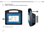
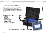
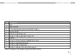
(see figure on „Fig.:
and interfaces“ on page 33, item 4). A suitable
Ethernet cable (cross-patch) for reading out the mea-
surement devices on site is included in the scope of
delivery.
The
Ethernet interface
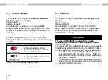
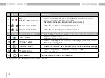
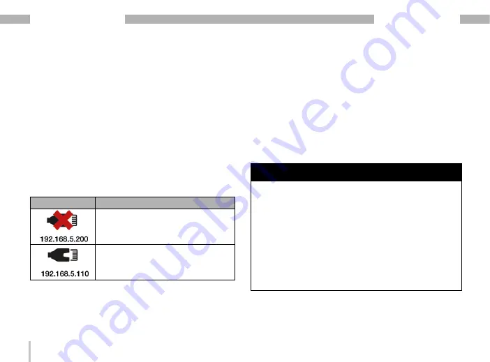
has no LED display. The
display shows the connection status with the following
symbols:
Display symbol Meaning
· Ethernet cable is missing.
· No connection to the network/
measurement device.
· Connection to the network/mea-
surement device.
Table: "Ethernet interface" display status
5. 3 USB port
The GridVis
®
Collector has a
USB 2.0 port
(see figure
and interfaces“ on page 33, item 3). The USB 2.0
port is used to transfer parameters when the GridVis
®
Collector is first commissioned and to connect the
USB/RS-485 converter.
ATTENTION
The use of USB/RS-485 converters from other
manufacturers can lead to communication errors or
material damage!
The use of third-party USB/RS-485 converters can lead to
a significantly higher current draw by the GridVis
®
Collec-
tor and thus lead to communication errors or destruction.
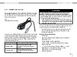
· For data transmission via RS-485 interfaces, use
only the USB/RS-485 converter (part no.: 15.06.107)
included in the scope of delivery for the connection to
the GridVis
®
Collector!
· If the USB/RS-485 converter is lost, please purchase
a new one from Janitza electronics GmbH and include
the part number in the order.
Summary of Contents for GridVis Collector
Page 25: ...25 www janitza de GridVis Collector...
Page 29: ...29 www janitza de GridVis Collector 270 mm 247 mm 91 mm Fig Housing of the GridVis Collector...
Page 37: ...37 www janitza de GridVis Collector...
Page 41: ...41 www janitza de GridVis Collector...
Page 45: ...45 www janitza de GridVis Collector...

