background image

4

www.janitza.de

Procont

®

-LMC-008-IO

TABLE OF CONTENTS

1.  Information on the device and the user manual . . . . . . . . . . . . . . . . . . . . . . . . . . . . . . . . . . . . . . . . 6

1.1 Disclaimer . . . . . . . . . . . . . . . . . . . . . . . . . . . . . . . . . . . . . . . . . . . . . . . . . . . . . . . . . . . . . . . . 6
1.2 

Copyright notice . . . . . . . . . . . . . . . . . . . . . . . . . . . . . . . . . . . . . . . . . . . . . . . . . . . . . . . . . . . 6

1.3 

Technical changes. . . . . . . . . . . . . . . . . . . . . . . . . . . . . . . . . . . . . . . . . . . . . . . . . . . . . . . . . . 6

1.4 

About this user manual . . . . . . . . . . . . . . . . . . . . . . . . . . . . . . . . . . . . . . . . . . . . . . . . . . . . . . 6

1.5 

Defective device/disposal . . . . . . . . . . . . . . . . . . . . . . . . . . . . . . . . . . . . . . . . . . . . . . . . . . . . 7

2. Safety . . . . . . . . . . . . . . . . . . . . . . . . . . . . . . . . . . . . . . . . . . . . . . . . . . . . . . . . . . . . . . . . . . . . . . . . . 8

2.1 

Display of warning notices and safety information . . . . . . . . . . . . . . . . . . . . . . . . . . . . . . . . . 8

2.2 

Hazard levels . . . . . . . . . . . . . . . . . . . . . . . . . . . . . . . . . . . . . . . . . . . . . . . . . . . . . . . . . . . . . . 8

2.3 

Product safety . . . . . . . . . . . . . . . . . . . . . . . . . . . . . . . . . . . . . . . . . . . . . . . . . . . . . . . . . . . . . 8

2.4 

Dangers when handling the device . . . . . . . . . . . . . . . . . . . . . . . . . . . . . . . . . . . . . . . . . . . . . 9

2.5 

Electrically qualified personnel . . . . . . . . . . . . . . . . . . . . . . . . . . . . . . . . . . . . . . . . . . . . . . . 10

2.6 

Warranty in the event of damage . . . . . . . . . . . . . . . . . . . . . . . . . . . . . . . . . . . . . . . . . . . . . 10

3.  Product description . . . . . . . . . . . . . . . . . . . . . . . . . . . . . . . . . . . . . . . . . . . . . . . . . . . . . . . . . . . . . 11

3.1 

Device description  . . . . . . . . . . . . . . . . . . . . . . . . . . . . . . . . . . . . . . . . . . . . . . . . . . . . . . . . 11

3.2 

Incoming goods inspection . . . . . . . . . . . . . . . . . . . . . . . . . . . . . . . . . . . . . . . . . . . . . . . . . . 11

3.3 

Intended use . . . . . . . . . . . . . . . . . . . . . . . . . . . . . . . . . . . . . . . . . . . . . . . . . . . . . . . . . . . . . 11

3.4 

EU conformity declaration  . . . . . . . . . . . . . . . . . . . . . . . . . . . . . . . . . . . . . . . . . . . . . . . . . . 11

3.5 

Scope of delivery  . . . . . . . . . . . . . . . . . . . . . . . . . . . . . . . . . . . . . . . . . . . . . . . . . . . . . . . . . 11

4.  Structure of the device . . . . . . . . . . . . . . . . . . . . . . . . . . . . . . . . . . . . . . . . . . . . . . . . . . . . . . . . . . . 12

4.1 

Display and connection assignments . . . . . . . . . . . . . . . . . . . . . . . . . . . . . . . . . . . . . . . . . . 12

4.2 

Operation and key functions . . . . . . . . . . . . . . . . . . . . . . . . . . . . . . . . . . . . . . . . . . . . . . . . . 13

4.3 

Rating plate . . . . . . . . . . . . . . . . . . . . . . . . . . . . . . . . . . . . . . . . . . . . . . . . . . . . . . . . . . . . . . 14

5.  Assembly and installation  . . . . . . . . . . . . . . . . . . . . . . . . . . . . . . . . . . . . . . . . . . . . . . . . . . . . . . . . 15

6. Connection . . . . . . . . . . . . . . . . . . . . . . . . . . . . . . . . . . . . . . . . . . . . . . . . . . . . . . . . . . . . . . . . . . . . 16

6.1 

Connecting the expansion module via a network . . . . . . . . . . . . . . . . . . . . . . . . . . . . . . . . . 16

6.2 

Connecting to the master . . . . . . . . . . . . . . . . . . . . . . . . . . . . . . . . . . . . . . . . . . . . . . . . . . . 17

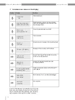
7.  Instantaneous values on the display . . . . . . . . . . . . . . . . . . . . . . . . . . . . . . . . . . . . . . . . . . . . . . . . 18

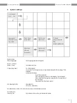
8.  System settings . . . . . . . . . . . . . . . . . . . . . . . . . . . . . . . . . . . . . . . . . . . . . . . . . . . . . . . . . . . . . . . . 19

9.  Alarms on the display . . . . . . . . . . . . . . . . . . . . . . . . . . . . . . . . . . . . . . . . . . . . . . . . . . . . . . . . . . . . 20

10. Network settings  . . . . . . . . . . . . . . . . . . . . . . . . . . . . . . . . . . . . . . . . . . . . . . . . . . . . . . . . . . . . . . . 21

Summary of Contents for Procont LMC-008-IO

Page 1: ...3 Janitza electronics GmbH Vor dem Polst ck 6 35633 Lahnau Germany Support tel 49 6441 9642 22 info janitza de www janitza de User manual and technical data www janitza de Extension module for load ma...

Page 2: ...2 www janitza de Procont LMC 008 IO Procont LMC 008 IO Extension module for load management Doc no 2 100 131 1 a Date 02 2023 The German version is the original edition of the documentation...

Page 3: ...reflect the current state of the information available to us Nonetheless we wish to point out that updates of this document are not always possible at the same time as technical refinements are imple...

Page 4: ...qualified personnel 10 2 6 Warranty in the event of damage 10 3 Product description 11 3 1 Device description 11 3 2 Incoming goods inspection 11 3 3 Intended use 11 3 4 EU conformity declaration 11 3...

Page 5: ...Dimensional drawings 24 11 2 Connection diagrams 25 11 2 1 Example Procont LMC 008 IO and boiler semiconductor contactor up to 4 25 11 2 2 Example Procont LMC 008 IO and relay contactor up to 8 26 12...

Page 6: ...erstood the usage information accompanying the prod uct Keep the usage information associated with the product available for the entire service life and pass it on to any possible subsequent users Fin...

Page 7: ...e shipping instructions for air or road freight complete with accessories Do not attempt to open or repair the device the component on your own because otherwise all warranty claims become invalid For...

Page 8: ...ed can result in minor or mod erate injury ATTENTION Warns of an immediately hazardous situation which if not avoided can result in material or envi ronmental damage INFORMATION Indicates procedures i...

Page 9: ...circuits when open Only connect screw terminals with the same number of poles and design Do not exceed the limit values specified in the user manual and on the rating plate This must also be observed...

Page 10: ...terial damage only electrically qualified personnel are permitted to work on the devices and their components mod ules assemblies systems and current circuits who have knowledge of The national and in...

Page 11: ...possible if the device for example Has visible damage No longer functions despite an intact power supply Was subjected to extended periods of unfavor able conditions e g storage outside of the per mi...

Page 12: ...s background illumination 2 LEDs for inputs 3 Relay outputs A8 A5 Outputs load groups 4 Digital inputs outputs Supply voltage 5 Status LED for relay outputs A1 A8 LED on output is active LED off outpu...

Page 13: ...s Device configuration Menu access To access the settings menu press the joystick to the right ENT for at least 1 second to return to the main menu press the joystick to the left ESC for at least 1 se...

Page 14: ...23 2 100 087 0 e 16 0f Aux 230V 50Hz 9VA PROCONT LMC 008 IO 6000303 10 2021 002 16 0f Aux 100 240V 50 60Hz 9 15VA PROCONT EMC 6000302 Janitza electronics GmbH Vor dem Polst ck 6 35633 Lahnau Germany M...

Page 15: ...twork Use a standard RJ45 patch cable to do so see also 4 1 Display and connection assignments on page 12 ATTENTION Material damage due to disregard of the instal lation instructions Disregard of the...

Page 16: ...l Close unused ports Take protective measures against viruses and cyber attacks from the Internet e g through firewall solutions security updates and virus protection programs Eliminate security vulne...

Page 17: ...must be set The station number is consecutive in a bus starting with 1 at the master module LMC LMC Lite A connection via TCP IP optionally available also requires the input of the IP address of the m...

Page 18: ...puts IP Adr IP addr IP Adr IP addr Display of the currently set IP address AZS M XP Mx 50 kW AZS M XP Mx 50 kW Type of the Procont LMC 008 IO and the maximum connected load BUS G 0 E Mob 0 BUS G 0 E M...

Page 19: ...Language Set language German English Datum Uhrzeit Date Time Set date and time T Sper Key lock N Not allowed If you want to change and save a parameter despite the message Not allowed proceed as foll...

Page 20: ...played here Alarm Error Ext Bus Bus failure of a bus device Not Aus Emergency stop Emergency stop alarm Emergency stop curve exceeded TCP Mod TCP module alarm The TCP module had an internal error Plea...

Page 21: ...n Spr Lng German Spr Lng German Grundb Home screen 1 Grundb Home screen 1 Spr Lng German Spr Lng German IP address Part1 2 IP address MASK P1 2 Subnet mask Gateway P1 2 Gateway address IP port 10001 M...

Page 22: ...ation the protective conductor must be connected Rated temperature range 0 C 32 F 40 C 104 F Relative air humidity non condensing 0 to 80 RH Operating elevation 0 2000 m 6562 ft above sea level Fasten...

Page 23: ...d services Modbus TCP Terminal connection capacity plug in Connectible conductors Only connect one conductor per terminal point Single core multi core fine stranded 0 2 2 5 mm2 AWG 26 12 Wire ferrules...

Page 24: ...r in Innenr umen bis max 2000m Seeh he 40 C Lagerung 20 bis 60 C 80 x I O Wahlweise Eing nge 24VDC 10mA Eingangsverz gerung 10ms max 25Hz oder Ausg nge 24VDC 50mA Relaiskontakte 6A 250VAC 6A 30VDC 1 W...

Page 25: ...ont LMC 008 IO and boiler semiconductor contactor up to 4 PROCONT LMC 008 IO PROCONT LMC 008 IO Potental free relais contacts 250 VAC 6 A Potental free relais contacts 250 VAC 6 A Control voltage 24 V...

Page 26: ...www janitza de Procont LMC 008 IO 11 2 2 Example Procont LMC 008 IO and relay contactor up to 8 PROCONT LMC 008 IO L1 L2 L3 N PE Seite 15 von 20 PROCONT LMC 008 IO L1 L2 L3 N PE Control voltage 24 VD...

Page 27: ...r questions please contact us directly We request the following information to ensure faster processing of your questions Device designation see rating plate Serial number see rating plate Firmware re...

Page 28: ...ject to technical alterations The current version of the document can be found in the download area at www janitza de Janitza electronics GmbH Vor dem Polst ck 6 35633 Lahnau Germany Tel 49 6441 9642...

Reviews: