26
UMG 605
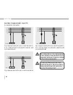
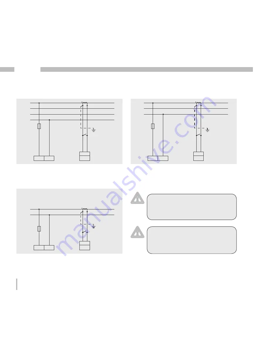
Auxiliary measurement, input V4
3-conductor connection
Fig. measurement with one current transform-
er in a three-phase 4 conductor network with
symmetrical load
Fig. measurement with one current transform-
er in a three-phase 3 conductor network with
symmetrical load.
Fig. measurement with one current transformer
m
In case of a three wire main mea-
surement (input V1-V3), the auxiliary
measurement (input V4) cannot be
used as measuring input.
Be connected for the measurement
of the auxiliary measurement (V4) for
frequency estimation needs a voltage
to the main measurement.
m
L1
L2
L3
N
L
4
N
4w 1m
I
4
S1 S2
L1
L2
L3
L
4
N
4w 1m
I
4
S1 S2
L
L
4
N
2w 1n
I
4
S1 S2
N
L1
L2
L3
N
L
4
N
4w 1m
I
4
S1 S2
L1
L2
L3
L
4
N
4w 1m
I
4
S1 S2
L
L
4
N
2w 1n
I
4
S1 S2
N
L1
L2
L3
N
L
4
N
4w 1m
I
4
S1 S2
L1
L2
L3
L
4
N
4w 1m
I
4
S1 S2
L
L
4
N
2w 1n
I
4
S1 S2
N
Summary of Contents for UMG 605
Page 29: ...29 UMG 605...
Page 33: ...33 UMG 605...
Page 45: ...45 UMG 605...
Page 79: ...79 UMG 605...
Page 89: ...89 UMG 605...
Page 90: ...90 UMG 605 Dimensioned drawings Front view Side view...


