background image

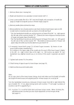
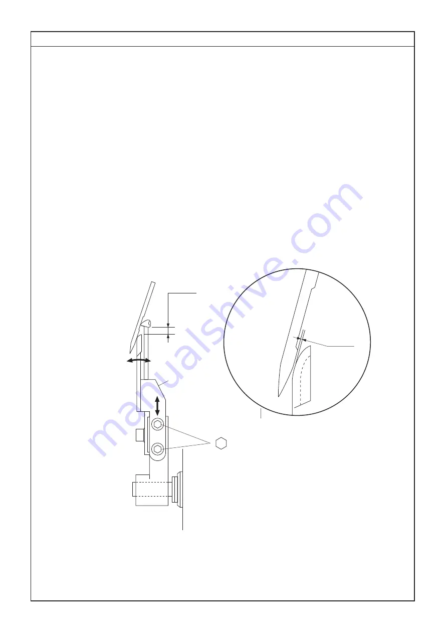
CLEARANCE OF NEEDLE GUARDS

7

2.7~3.4mm

2 mm

a

c

0~0.05mm

22

1. Remove: Mains lead - Needle plate.
2. Insert 2 new needles (No.90) in "R1" and "R2" positions.
3. Check height - clearance - angular position of lower looper.
4. Turn the handweel towardas you and bring needle bar in its lowest position.
5. Loosen screws "a".
6. Shift needle guard "c" back and forth to obtain a clearance of 0.05mm between
    needle guard "c" and needles, tighten both screws "a".

Summary of Contents for 1200D

Page 1: ...PARTS LIST SERVICE MANUAL MODEL 1200D First Edition 21 February 2019 ...

Page 2: ...SERVICE MANUAL ...

Page 3: ...to the needle plate holes 6 Height clearance angular position of lower looper 7 Clearance of needle guards 8 Timing of lower looper 9 Angular position of upper looper 10 Clearance and timing of upper looper to lower looper 11 Chain looper angular position clearance orbital timing clearance of chain needles guards 12 Chain looper thread take up rotary cam 13 Height of feed dog 14 Upper knife and ve...

Page 4: ... 705 H may be used However in certain cases stitch quality may be improved by using type ELX 705 needles Choose needle size No 80 for sheer materials and No 90 for normal or thick materials Threads Choose a good quality polyester thread or blended thread Lubrication Besides the 2 oiling points marked in red the machine is equipped with self lubrication bearings and parts Lubricate the machine as f...

Page 5: ...cation plate 2 For safety reasons never perform any repairs on the power supply circuit without first removing the mains lead from the machine 3 4 Never plug in or run the machine unless all the connections are correctly set When changing the light bulb it is neccessary to disconnect the mains lead 3 ...

Page 6: ... looper polish Burrs on chaining finger polish Excessive tension on the needle thread Height and orientation of needle bar Clearance between point of lower loopers and needle Clearance between upper and lower loopers Timing of upper and lower loopers against needle Feed timing 2 Skipped chainstitches Cover hems Check and adjust if necessary Needle and chain looper thread tensions not balanced Need...

Page 7: ...Irregular stitches Inadequate setting of thread tensions re adjust Unsmooth thread passage polish Height of feed dog Position of looper thread take up levers and thread guides Upper knife is dull replace Damage on needle plate face or presser foot sole replace Incorrect alignment of thread guide bar with spool pins reset it at correct position to align to spool pins 5 Breakage of needle Check and ...

Page 8: ...ADJUSTMENT OF THE AUTOMATIC TENSION UNIT D d B B r s 6 s r ...

Page 9: ...ion cam g Then tighten screw a 5 If the position of the display drum indicator d is not aligned with the display window e then loosen screw c and adjust the position of drum 6 Fasten screw c and recheck the position of the display drum d Note In order to check the alignment of the display drum indicator d and the disolay window e it is necessary to set the front cover on to machine POSITION OF PRO...

Page 10: ...M CHAINSTITCH 4 Bring the needle bar to its lowest position by turning a handwheel toword you 5 Loosen screw a and turn the upper looper shifting cam b until the hook of the looper follower c falls into the V shaped holl ow of the cam b ʻSee View A Check if a cam b and looper follower c are positioned as own in View B 6 Fasten screw a and recheck if the upper looper shifting connector d is pulled ...

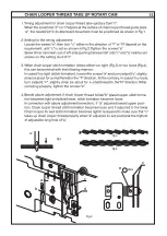
Page 11: ...to check the tension value with the tension gauge Brown tension 15 to 20 gr 5 If not adjust the tension value with the tension adjustment plate screw d Turn the screw d by one notch clockwise to increase or in reverse to decrease tension value 6 Make sure if a notch of the screw d faces against an indicator p See Fig 1 7 Set back a tension dial c with the mark N above into a shaft e See Fig 2 8 Fa...

Page 12: ... 12 0mm Height of needle bar 2 8mm Angular position of ower looper to needle 65 0mm Height of lower looper 5 6mm Angular position of upper looper to needle 1 5mm Chain looper angular position 46 0mm Position of upper looper thread take up lever 1 3mm Height of feed dogs 2 7mm Position of feed dog Gauge Nb 11951 Dimension Use ...

Page 13: ...1a REMOVING MACHINE BASE COVER 1 Remove Mains lead 2 Remove Machine base Unit 1 by loosening screws a 11 a 1 a a ...

Page 14: ...read guide Pole from Spool pin base 4 Remove screw caps and screws b and c from Back Cover 5 Remove Back Cover Unit 3 and Spool Stand 2 6 Remove Side Cover Note To remove screw caps use a wire pin No 11007 b 3 2 c 14mm 10mm No 11007 12 ...

Page 15: ...from Front Cover 4 Remove snap on Noise Cover Unit 6 Spread its side s 5 Remove screws a and Take up Noise Cover Bracket 8 with Allen Screw Driver 2 5mm 6 Position Needle Thread Take up Lever in the middle of the slot by turning handwheel toward you 7 Remove a screw e 8 Pull Front Cover towards you and remove it a 2 5mm d c b 7 9 6 8 e 13 ...

Page 16: ...RONT COVER When mounting covers please follow in reverse order pages 2b 2a 1 Note When mounting Snap on Noise Cover 6 in front cover make sure if a check spring takes its place in a slot as shown in view X 6 X view X 6 ...

Page 17: ...3a ANGULAR POSITION OF BALANCE WEIGHTS AND POSITION OF ECCENTRICS 6 7 7 8 8 3 2 6 1 3 2 a 5 4 1 4 4 Fig 3 Fig 4 Fig 5 Fig 6 Fig 7 A Fig 1 I O 7 Fig 2 8 2mm 15 ...

Page 18: ...3b ANGULAR POSITION OF BALANCE WEIGHTS AND POSITION OF ECCENTRICS 16 ...

Page 19: ... a HEIGHT AND ALIGNMENT OF CLOTH PRESSER BAR 4a 5 b c 4 7mm 17 ...

Page 20: ...of presser foot is in its highest position 5 Turn handwheel towards you and bring feed dog below needle plate 6 Loosen screw c 7 With lever a in its lowered position push cloth presser bar down from the top so that the presser foot touches gauge No 11951 8 Align the needle opening s of the presser foot with those of the needle plate and fasten screw c 9 Refit bracket with lamp holder 18 ...

Page 21: ...12 mm 0 2 R1 Fig 1 Fig 2 Fig 3 5a HEIGHT AND ORIENTATION OF NEEDLE BAR IN RELATION TO THE NEEDLE PLATE HOLES 19 5 b a A1 B1 A2 B2 A1 A2 B1 B2 ...

Page 22: ...t needle R1 grazes the gauge Fig 2 5 For the orientation of needle bar or needle holder insert new needles in L0 L1 and L2 orientate needle bar so that the needles are centered in the needle plate holes Make sure that neither needle L0 L1 nor L2 is touching the inside of the needle plate holes Tighten screw a and recheck the height Fig 3 6 Remove needle plate and check the clearance between the ch...

Page 23: ...o 90 in R1 and check height and orientation of needle bar 6 Remove needle plate and machinebase 7 Loosen screw b just enough to be able to shift lever c 8 Adjust lever c axially to obtain a clearance of less than 0 05mm between point of looper and needle See Fig 2 9 Turn the handwheel towards you and bring lower looper to its far left swing position and adjust lever c angularly to obtain 2 6 to 3 ...

Page 24: ...dles No 90 in R1 and R2 positions 3 Check height clearance angular position of lower looper 4 Turn the handweel towardas you and bring needle bar in its lowest position 5 Loosen screws a 6 Shift needle guard c back and forth to obtain a clearance of 0 05mm between needle guard c and needles tighten both screws a ...

Page 25: ...TIMING OF LOWER LOOPER 8a A B C D b a 5 2mm R1 Fig 1 Fig 2 Fig 3 23 ...

Page 26: ...TIMING OF LOWER LOOPER 8b 24 ...

Page 27: ...sition 4 Loosen screw d just enough so that lever e articulates with friction and adjust lever e angularly to obtain a 5 6mm gap between point of looper and the left side of the overlock needle 5 Tighten screw d It is very important that the machine turns quite freely without any biding effect caused by an axial shifting from lever e 6 Check clearance and timing of upper looper to lower looper 5 2...

Page 28: ...CLEARANCE AND TIMING OF UPPER LOOPER TO LOWER LOOPER 10 e 2 5mm 2mm b c d a f 0 05 0 2mm 1 0 1 5mm A B 26 ...

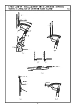
Page 29: ...1a CHAIN LOOPER ANGULAR POSITION CLEARANCE ORBITAL TIMING CLEARANCE OF CHAIN NEEDLES GUARD 1 5 1 8mm a c Fig 1 d e L2 L0 Fig 2 Fig 5 Fig 3 Motion L2 L0 0 0 05mm 1 0 2 0mm 0 0 05mm Fig 4 e 0 0 1mm f f 27 ...

Page 30: ... 5 See pag e 3a 3b for th e positio n of eccentric The eccentric 5 isused for both chain and lower looper timin g When adjusting thistiming make sure that you also check the adjustment of lower looper stroke See page 6 and 8 4 Clearance of chain looper Bring point of loope r from right to left behind the cover hem needle L2 and check if clearance islessthan 0 05mm Then bring tip of loope r behind ...

Page 31: ...11c CHAIN LOOPER ANGULAR POSITION CLEARANCE ORBITAL TIMING CLEARANCE OF CHAIN NEEDLES GUARD d c Fig 8 R1 Fig 7 b c g d Fig 6 1 0 1 0mm Fig 9 Motion 2 2 1 1 ...

Page 32: ...CHAIN LOOPER ANGULAR POSITION CLEARANCE ORBITAL TIMING CLEARANCE OF CHAIN NEEDLES GUARD 11d ...

Page 33: ...ts lowerst position Lift up lever A to disengage chain looper Turn handwheel towards you again and check if chain looper is automatically engaged If not loosen screw h and slide the plate b right or left to get the gap 0 5 2 0mm as shown in Fig 13 Note If either lower looper or chain looper is set apart from the plate b so far or if either of two touches the plate b handwheel is blocked and can no...

Page 34: ...Fig 2 Fig 1 R F 2mm L2 c d e c a b Fig 4 Fig 3 ...

Page 35: ......

Page 36: ...R1 A a B d c Fig 2 Fig 4 Fig 3 Fig 1 2mm 0 5 0 5mm 0 5 0 8mm ...

Page 37: ......

Page 38: ......

Page 39: ......

Page 40: ......

Page 41: ......

Page 42: ......

Page 43: ......

Page 44: ......

Page 45: ......

Page 46: ......

Page 47: ...21c ...

Page 48: ......

Page 49: ...ANNEX TOOLS FOR SETTING SL DF DIALS 1 5 1 0 R2 37 1 0 2 0 47 Fig 2 84 48 12 10 3 12 2 6 6 Tool A part No 11960 Tool B part No 11961 ...

Page 50: ...ANNEX SETTING POSITIONS OF SL DF DIALS a Fig 1 48 A b a ...

Page 51: ...ANNEX SETTING POSITIONS OF SL DF DIALS b c d g e 2 1 1 C B A 49 ...

Page 52: ...ANNEX SETTIN POSITIONS OF SL DF DIALS c 50 ...

Page 53: ...d ANNEX SETTING POSITIONS OF SL DF DIALS h i Z k j p SL Dial DF Dial Fig 3 Fig 4 i A n k a Fig 2 view Z view Z 51 ...

Page 54: ... tool A gose through 9 Check and make sure if the hook of the looper follower c falls into the V shaped hollow of the upper looper shifting cam b See adjustment of the page F POSITION OF THE PDISPLAY DRUM INDICATOR UPPER LOOPER SHIFTING CAM and view A Tighten screw a 10 If stopper spring plate p gives too heavy or light pressure on SL dial loosen screw n and adjust the position of stopper spring p...

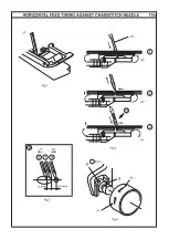
Page 55: ...l towards you until feed dog moves to far rear position Loosen screw k and move feed bar m back and forth to obtain a clearance F of 0 3 to 0 5mm Fig 1 Fasten screw k 2 Turn the handwheel towards you until feed dog moves to far front position Check and make sure if a clearance between feed dog and needle plate is 0 7mm Fig 2 0 7 Fig 1 0 3 0 5mm Fig 2 3mm F m k ...

Page 56: ...Fig 1 then check the following points 2 Insert new needles No 90 3 Check and make sure that needles are correctly inserted into the needle clamp 4 Check and make sure that the needle L0 or L1 is not touching the needle plate holes If necessary check adjustment on page 3 Height and orientation of needle bar in relation to the needle plate holes a ...

Page 57: ...Fig 3 Fig 4 Fig 5 Fig 6 Red L1 Y ellow L2 Red L1 Y ellow L2 Blue L0 Y ellow L2 Blue L0 Red L1 Y ellow L2 Blue L0 Red L1 Y ellow L2 ANNEX TROBLE SHOOTING COVER HEMS irregular loop formation on the chain needles b 55 ...

Page 58: ... If L2 needle falls into its needle thread loop Fig 1 2 Check position of chainstitch eccentric 0 5 1 0mm See page 11 for adjustment Check clearance between chain looper and L0 L1 needle If the problem is not solved replace chain looper 2 Triple Cover Hem If L2 needle falls into the Red needle thread loop Fig 3 Check if the tension is correctly set Check the chain looper clearance and orbital timi...

Page 59: ...ass into needle thread loops Fabric move forward to the next stitch and chain looper move to the front of the needles Needles go down into thethread triangle and chain looper is moving to the right Chain looper is releasing needle thread loops Needles are in the lowest position and chain looper is set at the extreme right position a 57 ...

Page 60: ...ass into needle thread loops Fabric move forward to the next stitch and chain looper move to the front of the needles Needles go down into the thread triangle and chain looper is moving to the right Chain looper is releasing needle thread loops Needles are in the lowest position and chain looper is set at the extreme right position b 58 ...

Page 61: ...A 6 Attach the TB SW unit to the motor bracket Be sure to insert the insulation plate between the TB SW unit and motor bracket for 220V motor attach the condenser cover instead 7 Attach the new motor to the motor bracket Connect the 2 connectors e and t to the micro switch of the safety device Connect the other connectors q and w to the lamp leads 8 Adjust the motor belt tension and tighten the nu...

Page 62: ......

Page 63: ...PARTS LIST MODEL 1200D First Edition 28 February 2019 ...

Page 64: ...2 MODEL 1200D PARTS LIST 16 15 14 17 18 19 20 21 22 23 24 25 26 27 28 29 30 31 745 12 13 ...

Page 65: ...0103509 797029109 000101703 797611001 797028108 797501007 000129903 000062402 Front cover unit Front cover Upper thread guide CS top thread guide CS thread base guide Needle thread guide Check spring stud Check spring Snap ring CS 4 Program display 1 Program display 2 Program display 3 Sticker LED unit LED holder Setscrew 3x8 B Setscrew TP 4x6 Cap Setscrew TP 4x12 Take up lever noise cover Needle ...

Page 66: ...4 MODEL 1200D PARTS LIST 33 30 34 31 32 34 37 39 38 39 36 40 18 19 20 21 24 25 14 13 11 12 17 1 2 3 28 29 10 9 9 4 27 27 26 26 6 7 8 5 35 35 15 16 22 23 ...

Page 67: ...107 797066005 000133807 000101404 Back cover set unit Back cover thread guide unit Back cover Top thread guide unit Top thread guide base Top thread guide Top thread guide button Top thread guide cushion Washer 3 Setscrew 3x8 B Spool stand unit Spool stand Spool pin Spool holder Setscrew 4x16 P Antenna unit Thread guide pole unit Thread guide antenna Antenna flap hinge Toothed lock washer 4 Setscr...

Page 68: ...6 MODEL 1200D PARTS LIST 1 2 3 4 5 6 7 8 9 10 11 12 13 14 15 16 17 17 18 19 19 ...

Page 69: ...612105 797007709 797017001 797018002 797090008 797091009 797092000 000002105 797009103 000134406 Base cover unit Base cover Rubber foot Washer 4 Setscrew 3 5x12 B cover spring Nut Setscrew TP 3x10 Setscrew TP 4x12 Front flap unit Front flap Threading chart 1 Threading chart 2 Front flap hinge Front flap hinge shaft spring Front flap hinge shaft Snap ring E 3 Overlock sewing table Setscrew 4x10 ...

Page 70: ...6 13 14 15 17 18 20 54 21 70 9 7 53 30 29 42 37 41 9 26 35 34 33 32 31 36 39 29 30 19 24 23 25 22 55 69 17 53 9 42 56 53 58 9 57 60 59 62 64 65 18 42 63 61 38 66 67 9 16 9 16 9 16 16 37 38 38 27 28 37 37 38 68 51 50 43 44 45 48 49 9 46 47 52 2 1 40 64 ...

Page 71: ... Setscrew 3x5 DT support shaft Snap ring CS 3 DT cam shaft Snap ring E 4 Dial tension cam yellow Dial tension cam blue Dial tension cam red Dial tension cam green Tension cam lever Tension cam spring Polyslider thrust washer DT flywheel Hexagonal socket screw 4x4 Fixed blade support holder Tension release lever Tension release leer spring Hexagonal socket screw 4x8 Tension release crank Hexagonal ...

Page 72: ...10 MODEL 1200D PARTS LIST 36 41 42 43 44 45 46 26 27 28 29 30 38 31 40 39 32 33 34 35 37 33 34 22 23 24 25 ...

Page 73: ...foot shank Setscrew 7x8 Presser bar Presser bar guide unit Presser bar guide Presser bar spring Hexagonal socket screw 4x4 Presser adjustment base holder unit Presser adjustment base holder Presser control dial Snap ring E 4 Presser bar lift crank Friction washer 6 Needle bar presser ft safety cam sleeve Washer FT120 Presser foot lever set unit Presser foot lever unit Knob spring Setscrew 4x10 Pre...

Page 74: ...12 MODEL 1200D PARTS LIST 1 2 10 27 24 24 4 4 3 11 26 22 20 19 27 28 7 6 5 15 18 17 14 13 13 12 16 16 29 21 25 23 9 8 30 ...

Page 75: ...797042005 000081005 797041004 797056002 797347003 Reflex partition plate unit Reflex partition plate Safety lever cam Snap ring E 3 Triangle thread guide lever Triangle thread guide Coin screw Cam spring B Snap ring E 4 Top cover guide cam Hexagonal socket screw 4x4 Top cover hook lever spring Washer Bearing Top cover hook lever Hexagonal socket screw 3x6 Pillow ball Snap ring E 5 Micro switch for...

Page 76: ...14 MODEL 1200D PARTS LIST 1 2 3 4 5 6 6 6 6 9 4 7 8 4 10 10 10 4 4 4 10 4 4 ...

Page 77: ...9 10 797031115 797032002 797033003 000111201 797034004 797035005 797036006 000128304 797037007 797038008 Casing Upper needle bar bearing Lower needle bar bearing Hexagonal socket screw 4x4 Presser bar bearing Bearing Holding spring Setscrew 4x8 Bearing Looper axle bearing ...

Page 78: ...16 MODEL 1200D PARTS LIST 2 8 9 10 11 12 41 43 44 42 44 45 40 15 33 34 15 31 36 35 15 37 38 37 32 28 15 29 26 25 26 31 15 30 15 15 14 17 15 16 15 19 15 18 22 23 15 15 21 20 27 24 39 15 7 6 3 4 5 13 ...

Page 79: ... 000104706 Main shaft unit Main shaft Spring pin 3x16 Washer FT80x1 0 Snap ring C 8 STW Pulley unit Pulley Pulley ballance Setscrew 3x8 B Hexagonal socket bolt 4x20 SW Cap Belt XL136 Main shaft ballancer left unit Main shaft ballancer left Hexagonal socket screw 4x4 Eccentric unit Eccentric CS eccentric unit CS eccentric Crank cam unit Crank cam Looper rod eccentric unit Looper rod eccentric Rotar...

Page 80: ...18 MODEL 1200D PARTS LIST 43 8 44 45 46 47 47 48 49 50 50 51 52 56 57 58 59 60 61 62 63 64 65 66 67 68 69 70 71 72 73 74 75 76 77 77 78 79 80 80 53 54 55 ...

Page 81: ...nt pin Upper looper oscillating crank Hexagonal socket screw 5x5 Spacer Hexagonal socket bolt 5x18 Ball rod unit Washer FT70x0 5 Upper looper arm 2 Upper looper arm 1 Hexagonal socket bolt 4x10 Looper bar Upper looper shaft pin Hexagonal socket screw 4x4 Upper looper take up lever unit Upper looper take up lever Upper thread guide Conical washer Hexagonal socket screw 4x6 Looper guide unit Looper ...

Page 82: ...20 MODEL 1200D PARTS LIST ...

Page 83: ...t Feed bar unit Feed bar Feed rod Feed eccentric pin Snap ring E 6 Hexagonal socket screw 4x4 Main feed dog Hexagonal socket bolt 4x10 Guide pin Differential feed dog Feed bar shaft Link pin Feed bar conn pin Washer FT50x0 5 Snap ring E 4 Feed rock lever back unit Feed rock lever back Feed rock lever left Hexagonal socket screw 4x3 FR regulator rod DF connection rod DF shaft arm Snap ring E 3 DF r...

Page 84: ...22 MODEL 1200D PARTS LIST ...

Page 85: ... 797197006 797198007 000002105 797199008 797200003 797201004 797202005 000081005 Dial support unit Dial support DF notch spring plate Setscrew 3x3 Stopper spring plate Setscrew 4x6 S L D F dial shaft S L Dial S L D F Dial gear Washer 6 Snap ring E 5 D F Dial Washer 6 Collar 6 Hexagonal socket screw 3x3 Upper looper shifting lever Upper looper shifting connector Snap ring E 3 Follower shaft Release...

Page 86: ...24 MODEL 1200D PARTS LIST ...

Page 87: ...7282009 000001609 797283000 797012109 797108000 000115700 Upper knife unit Knife holder Pin Upper knife shaft Dry lock allen screw 3x3 Upper knife spring Upper knife dial Hexagonal socket screw 4x4 Upper knife holder Upper knife Hexagonal socket bolt 4x10 Knife arm U Knife arm shaft U Washer FT60x0 5 Snap ring C 6 STW Collar 6 Hexagonal socket screw 3x3 Pin Knife arm L Knife arm shaft L Washer FT7...

Page 88: ...26 MODEL 1200D PARTS LIST 7 2 3 4 5 6 1 8 ...

Page 89: ... 797551002 795651030 795181001 508512504 795182002 000120203 000081005 000115700 Machine socket unit Printed circuit board C case unit Printed circuit board C case Printed circuit board C unit Printed circuit board C case cover Setscrew 3x8 B Setscrew 4x8 Setscrew TP4x10 ...

Page 90: ...28 MODEL 1200D PARTS LIST 1 2 3 4 5 6 9 13 14 15 10 11 12 16 19 20 21 17 18 22 23 24 26 7 8 25 ...

Page 91: ...003 797008102 797821006 797364006 797863000 797848009 C 2078 797842003 797852006 797843004 797608005 Accessory set Accessory case unit Accessory case Tension release clip Spool cap Lint brush Wrench M4 Oil Thread guide Needle threader Upper knife Tweezers Needle clamp screwdriver Needle set Top cover foot R Waste chip box Chain stitch sewing table Foam pad Threading reference chart Sticker Referen...

Reviews: