MODEL 1200D
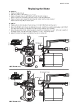
To Remove:
1. Remove the back cover.
2. Disconnect the 4 connectors (
q
,
w
,
e
,
t
).
3. Remove the setscrews C and TB/SW unit from the motor bracket.
Remove the nut A and remove the motor lead
r
from the TB/SW unit.
4. Remove the nuts (or screws) B and remove the motor from the motor bracket.
Remove the motor pulley from the motor.
To Attach:
5. Replace the motor and attach the motor lead
r
to the TB/SW unit with the nut A.
6. Attach the TB/SW unit to the motor bracket. Be sure to insert the insulation plate between the TB/SW
unit and motor bracket. (*for 220V motor, attach the condenser cover instead)
7. Attach the new motor to the motor bracket. Connect the 2 connectors
e
and
t
to the micro switch of
the safety device. Connect the other connectors
q
and
w
to the lamp leads.
8. Adjust the motor belt tension and tighten the nuts (or screws) B.
Replacing the Motor
e
r
q
w
q
w
t
e
r
C
A
B
Insulation plate
q
w
e
t
r
120V Motor unit
220V Motor unit
e
r
q
w
A
q
w
t
e
C
r
r
B
q
w
e
t
Condenser Cover
Motor pulley
Motor pulley
TB/SW unit
TB/SW unit
Summary of Contents for 1200D
Page 1: ...PARTS LIST SERVICE MANUAL MODEL 1200D First Edition 21 February 2019 ...
Page 2: ...SERVICE MANUAL ...
Page 8: ...ADJUSTMENT OF THE AUTOMATIC TENSION UNIT D d B B r s 6 s r ...
Page 18: ...3b ANGULAR POSITION OF BALANCE WEIGHTS AND POSITION OF ECCENTRICS 16 ...
Page 19: ... a HEIGHT AND ALIGNMENT OF CLOTH PRESSER BAR 4a 5 b c 4 7mm 17 ...
Page 25: ...TIMING OF LOWER LOOPER 8a A B C D b a 5 2mm R1 Fig 1 Fig 2 Fig 3 23 ...
Page 26: ...TIMING OF LOWER LOOPER 8b 24 ...
Page 32: ...CHAIN LOOPER ANGULAR POSITION CLEARANCE ORBITAL TIMING CLEARANCE OF CHAIN NEEDLES GUARD 11d ...
Page 34: ...Fig 2 Fig 1 R F 2mm L2 c d e c a b Fig 4 Fig 3 ...
Page 35: ......
Page 36: ...R1 A a B d c Fig 2 Fig 4 Fig 3 Fig 1 2mm 0 5 0 5mm 0 5 0 8mm ...
Page 37: ......
Page 38: ......
Page 39: ......
Page 40: ......
Page 41: ......
Page 42: ......
Page 43: ......
Page 44: ......
Page 45: ......
Page 46: ......
Page 47: ...21c ...
Page 48: ......
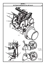
Page 50: ...ANNEX SETTING POSITIONS OF SL DF DIALS a Fig 1 48 A b a ...
Page 51: ...ANNEX SETTING POSITIONS OF SL DF DIALS b c d g e 2 1 1 C B A 49 ...
Page 52: ...ANNEX SETTIN POSITIONS OF SL DF DIALS c 50 ...
Page 62: ......
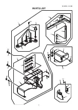
Page 63: ...PARTS LIST MODEL 1200D First Edition 28 February 2019 ...
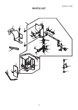
Page 64: ...2 MODEL 1200D PARTS LIST 16 15 14 17 18 19 20 21 22 23 24 25 26 27 28 29 30 31 745 12 13 ...
Page 68: ...6 MODEL 1200D PARTS LIST 1 2 3 4 5 6 7 8 9 10 11 12 13 14 15 16 17 17 18 19 19 ...
Page 76: ...14 MODEL 1200D PARTS LIST 1 2 3 4 5 6 6 6 6 9 4 7 8 4 10 10 10 4 4 4 10 4 4 ...
Page 82: ...20 MODEL 1200D PARTS LIST ...
Page 84: ...22 MODEL 1200D PARTS LIST ...
Page 86: ...24 MODEL 1200D PARTS LIST ...

