Janome 3128, Service Manual
The Nokia 3128 is a feature-packed mobile device that offers all the functionality you need. To ensure hassle-free usage, we provide a comprehensive User Manual that can be downloaded for free from our website. Enhance your experience with the Nokia 3128 by accessing the detailed manual at 88.208.23.73:8080.
Share
Download

Reviews:
No comments
Related manuals for 3128

B-1500
Brand: Pacific Pages: 8

KX-TG2248S - 2.4 GHz Digital Cordless Phone Answering...
Brand: Panasonic Pages: 35
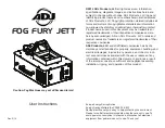
FOG FURY JETT
Brand: ADJ Pages: 10

UnionSpecial 35800BLWG
Brand: JUKI Pages: 68

Embroidery Professional BMP8
Brand: Baby Lock Pages: 11

550-12
Brand: Duerkopp Adler Pages: 80

QTFX-700
Brand: QTX Light Pages: 7

Fax PA 300
Brand: T-COM Pages: 6

AB900
Brand: Amplicom Pages: 4
Argenta
Brand: Azkoyen Pages: 88

NI EVS-1463
Brand: National Instruments Pages: 12

8768
Brand: Singer Pages: 61

SircleBind CC-320
Brand: Sirclecorp Pages: 6

Easy Step Plus MS 80
Brand: Impex Pages: 9

LT5-H710-1
Brand: Unicorn Pages: 28

Adgressor BR 1050CS
Brand: Nilfisk-Advance Pages: 82

SD-10
Brand: BRONDI Pages: 32

1600
Brand: Rosco Pages: 50


