background image

MODEL 3128

17

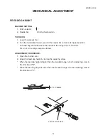
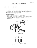
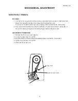
BUTTONHOLE FEED BALANCE

TO CHECK:

When sewing buttonhole, the stitches on each side of buttonhole stitch density should be the
same.

The range of 9 - 11 stitches in the right side row 

"

backward feeding

"

 against 10 stitches in the

left side row 

"

forward feeding

"

 is considered acceptable.

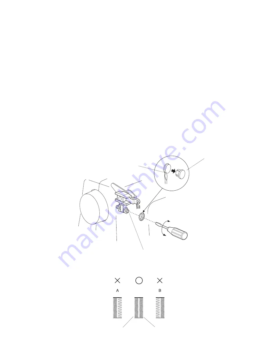
ADJUSTMENT PROCEDURE:

1. Confirm the stitches by sewing buttonholes, and remove the cap.
2. Turn the adjusting screw in the direction of "C" in case of "A" (right stitches are rough), or

in the direction of "D" in case of "B" (left stitches are rough).

3. Mount the cap.

MECHANICAL ADJUSTMENT

CAP

NOTCH

ADJUSTING SCREW

D

C

FORWARD FEEDING

BACKWARD FEEDING

Summary of Contents for 3128

Page 1: ...SERVICE MANUAL MODEL 3128...

Page 2: ...EIGHT AND ALIGNMENT 9 NEEDLE SWING 10 NEEDLE DROP 11 CLEARANCE BETWEEN NEEDLE AND HOOK NO 1 12 CLEARANCE BETWEEN NEEDLE AND HOOK NO 2 13 FEED DOG HEIGHT 14 NEEDLE BAR HEIGHT 15 NEEDLE TIMING TO SHUTTL...

Page 3: ...ropriate needle bar See mechanical adjustment P 15 height Needle bar height 7 Inappropriate needle to See mechanical adjustment P 16 hook timing Needle timing to shuttle 8 Inappropriate needle to See...

Page 4: ...read for fabric in use 6 Needle eye is worn Change the needle 7 Needle hole in needle Repair the hole or replace the plate is worn or burred needle plate 4 Breaking 1 Incorrectly threaded Thread bobbi...

Page 5: ...hile sewing while sewing 6 Noisy 1 Backlash between shuttle See mechanical adjustment P 13 Operation hook gear and lower shaft Clearance between needle gear is too great and hook No 2 2 Lower shaft ge...

Page 6: ...ERVICE ACCESS TO REMOVE 1 Remove the setscrew A 2 Take the face cover B off Note When removing the face cover pull it up and unhook from the hook C TO ATTACH 3 Follow the above procedure in reverse C...

Page 7: ...SS REAR COVER TO REMOVE 1 Remove the face cover see page 4 2 Remove the setscrews A B C D E and rubber cushion F 2 pcs and then remove the rear cover TO ATTACH 3 Follow the above procedure in reverse...

Page 8: ...ce cover and rear cover see pages 4 5 2 Pull out the pattern selector dial 3 Loosen the setscrews A B and remove the setscrews C D and the rubber cushion E then remove the front cover TO ATTACH 4 Foll...

Page 9: ...3 Make sure the foot should be lowered If the tension is out of the standard range adjust it as follows ADJUSTMENT PROCEDURE 1 Remove the front cover see page 6 2 Turn the adjusting nut B in the direc...

Page 10: ...5 55g when pulling the thread in the direction of A If the tension is out of the range adjust it as follows ADJUSTMENT PROCEDURE 1 Turn the adjusting screw B in the direction of C when the bobbin thre...

Page 11: ...the lamp A off 3 Raise the presser foot lever and loosen the setscrew B on the presser bar holder Adjust the distance between the presser foot C and the needle plate D to 6 0mm 0 24 4 Tighten the sets...

Page 12: ...he front cover see page 6 2 Loosen two setscrews 3 Adjust the needle swing by turning the handwheel while holding the worm so as not to rotate it until the needle swing starts at 2 3 mm above the need...

Page 13: ...should be equal If not make an adjustment as follows ADJUSTMENT PROCEDURE 1 Remove the face cover see page 4 2 Set the pattern selector dial at maximum zigzag width position 3 Turn the setscrew to ad...

Page 14: ...e direction of arrow as shown below and adjust the clearance between needle and shuttle hook to 0 0 15 mm tighten setscrews If the clearance is too large more than 0 1 mm slide the needle bar supporte...

Page 15: ...and slightly move the shuttle body up or down to adjust the clearance between needle and shuttle hook to 0 05 0 10 mm and tighten the setscrews B temporary 4 Turn the handwheel to check the clearance...

Page 16: ...needle in the range of 0 75 0 90 mm If it is not in the range adjust as follows ADJUSTMENT PROCEDURE 1 Open the shuttle cover 2 Adjust the feed dog height by turning the adjusting screw When the feed...

Page 17: ...4 2 Set the pattern selector dial at maximum zigzag with and needle drop position is at left 3 Open the shuttle cover 4 Remove the shuttle race ring 5 Turn the handwheel toward you until the tip of t...

Page 18: ...race ring 5 Turn the handwheel toward you until the tip of the shuttle hook meets the left side of the needle 6 Loosen the lower shaft crank arm setscrews A 7 While holding the shuttle hook so it does...

Page 19: ...inst 10 stitches in the left side row forward feeding is considered acceptable ADJUSTMENT PROCEDURE 1 Confirm the stitches by sewing buttonholes and remove the cap 2 Turn the adjusting screw in the di...

Page 20: ...indered with the zigzag cam block when you turn the pattern selector dial 1 Sew a buttonhole and check the difference in both line tack widths 2 Remove the front cover see page 6 3 Adjust the line tac...

Page 21: ...eeth on the motor pulley 2 The correct motor belt tension is that the deflection of motor belt is about 7 mm 0 28 9 mm 0 36 when pushing the motor belt by finger at about 300 grams load ADJUSTMENT PRO...

Page 22: ...MODEL 3128 20 WIRING FOR MACHINE SOCKET UNIT WIRING M MOTOR L LAMP P POWER SWITCH M L P...

Page 23: ...needs whenever servicing machines OIL Use good quality sewing machine oil at the points A B C D E indicated by black arrows GREASE The white grease is recommended for use on all model sewing machines...

Reviews: