background image

MODEL 3128

20

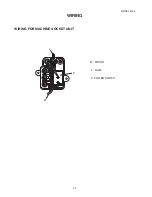
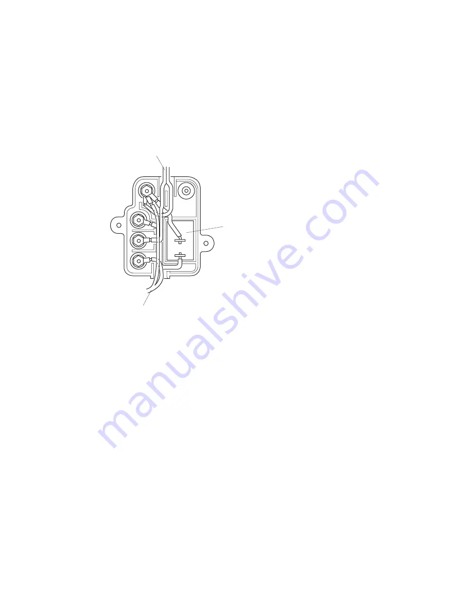
WIRING FOR MACHINE SOCKET UNIT

WIRING

M : MOTOR

 L : LAMP

 P : POWER SWITCH

M

L

P

Summary of Contents for 3128

Page 1: ...SERVICE MANUAL MODEL 3128...

Page 2: ...EIGHT AND ALIGNMENT 9 NEEDLE SWING 10 NEEDLE DROP 11 CLEARANCE BETWEEN NEEDLE AND HOOK NO 1 12 CLEARANCE BETWEEN NEEDLE AND HOOK NO 2 13 FEED DOG HEIGHT 14 NEEDLE BAR HEIGHT 15 NEEDLE TIMING TO SHUTTL...

Page 3: ...ropriate needle bar See mechanical adjustment P 15 height Needle bar height 7 Inappropriate needle to See mechanical adjustment P 16 hook timing Needle timing to shuttle 8 Inappropriate needle to See...

Page 4: ...read for fabric in use 6 Needle eye is worn Change the needle 7 Needle hole in needle Repair the hole or replace the plate is worn or burred needle plate 4 Breaking 1 Incorrectly threaded Thread bobbi...

Page 5: ...hile sewing while sewing 6 Noisy 1 Backlash between shuttle See mechanical adjustment P 13 Operation hook gear and lower shaft Clearance between needle gear is too great and hook No 2 2 Lower shaft ge...

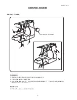
Page 6: ...ERVICE ACCESS TO REMOVE 1 Remove the setscrew A 2 Take the face cover B off Note When removing the face cover pull it up and unhook from the hook C TO ATTACH 3 Follow the above procedure in reverse C...

Page 7: ...SS REAR COVER TO REMOVE 1 Remove the face cover see page 4 2 Remove the setscrews A B C D E and rubber cushion F 2 pcs and then remove the rear cover TO ATTACH 3 Follow the above procedure in reverse...

Page 8: ...ce cover and rear cover see pages 4 5 2 Pull out the pattern selector dial 3 Loosen the setscrews A B and remove the setscrews C D and the rubber cushion E then remove the front cover TO ATTACH 4 Foll...

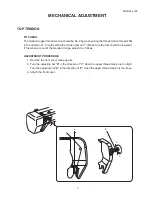
Page 9: ...3 Make sure the foot should be lowered If the tension is out of the standard range adjust it as follows ADJUSTMENT PROCEDURE 1 Remove the front cover see page 6 2 Turn the adjusting nut B in the direc...

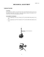
Page 10: ...5 55g when pulling the thread in the direction of A If the tension is out of the range adjust it as follows ADJUSTMENT PROCEDURE 1 Turn the adjusting screw B in the direction of C when the bobbin thre...

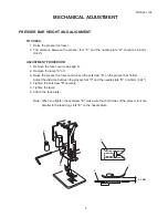
Page 11: ...the lamp A off 3 Raise the presser foot lever and loosen the setscrew B on the presser bar holder Adjust the distance between the presser foot C and the needle plate D to 6 0mm 0 24 4 Tighten the sets...

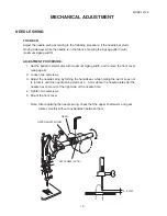
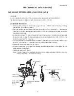
Page 12: ...he front cover see page 6 2 Loosen two setscrews 3 Adjust the needle swing by turning the handwheel while holding the worm so as not to rotate it until the needle swing starts at 2 3 mm above the need...

Page 13: ...should be equal If not make an adjustment as follows ADJUSTMENT PROCEDURE 1 Remove the face cover see page 4 2 Set the pattern selector dial at maximum zigzag width position 3 Turn the setscrew to ad...

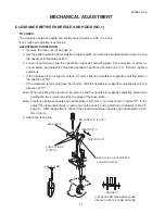
Page 14: ...e direction of arrow as shown below and adjust the clearance between needle and shuttle hook to 0 0 15 mm tighten setscrews If the clearance is too large more than 0 1 mm slide the needle bar supporte...

Page 15: ...and slightly move the shuttle body up or down to adjust the clearance between needle and shuttle hook to 0 05 0 10 mm and tighten the setscrews B temporary 4 Turn the handwheel to check the clearance...

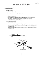
Page 16: ...needle in the range of 0 75 0 90 mm If it is not in the range adjust as follows ADJUSTMENT PROCEDURE 1 Open the shuttle cover 2 Adjust the feed dog height by turning the adjusting screw When the feed...

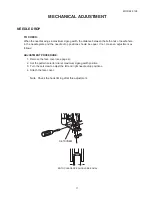
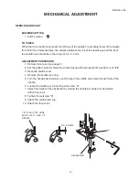
Page 17: ...4 2 Set the pattern selector dial at maximum zigzag with and needle drop position is at left 3 Open the shuttle cover 4 Remove the shuttle race ring 5 Turn the handwheel toward you until the tip of t...

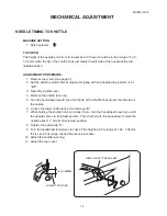
Page 18: ...race ring 5 Turn the handwheel toward you until the tip of the shuttle hook meets the left side of the needle 6 Loosen the lower shaft crank arm setscrews A 7 While holding the shuttle hook so it does...

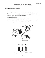
Page 19: ...inst 10 stitches in the left side row forward feeding is considered acceptable ADJUSTMENT PROCEDURE 1 Confirm the stitches by sewing buttonholes and remove the cap 2 Turn the adjusting screw in the di...

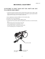
Page 20: ...indered with the zigzag cam block when you turn the pattern selector dial 1 Sew a buttonhole and check the difference in both line tack widths 2 Remove the front cover see page 6 3 Adjust the line tac...

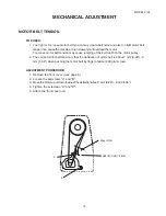
Page 21: ...eeth on the motor pulley 2 The correct motor belt tension is that the deflection of motor belt is about 7 mm 0 28 9 mm 0 36 when pushing the motor belt by finger at about 300 grams load ADJUSTMENT PRO...

Page 22: ...MODEL 3128 20 WIRING FOR MACHINE SOCKET UNIT WIRING M MOTOR L LAMP P POWER SWITCH M L P...

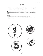
Page 23: ...needs whenever servicing machines OIL Use good quality sewing machine oil at the points A B C D E indicated by black arrows GREASE The white grease is recommended for use on all model sewing machines...

Reviews: