19
MECHANICAL ADJUSTMENT
REPLACING AND ADJUSTING THE PRESSER FOOT LIFTER SWITCH UNIT
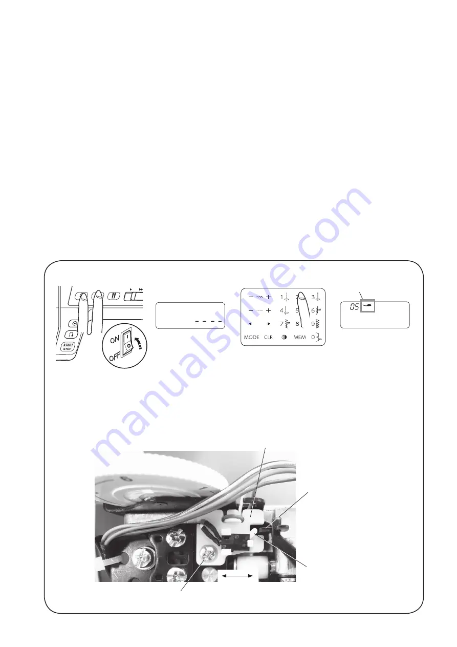
To replace:
1. Remove the front cover and rear cover (see pages 5 to 7).
2. Remove the setscrew, replace the presser foot lifter switch.
To adjust:
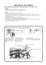
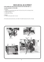
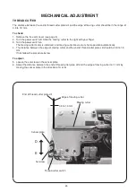
3. Raise the presser foot lifter. Loosen the setscrew.
Move the presser foot lifter switch in the direction of the arrows to adjust the position of the switch.
The switch lever of the presser foot lifter switch should be pressed by the thread tension release lever.
Tighten the setscrew.
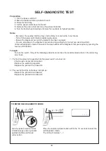
4. Enter the presser foot lifter switch adjusting mode.
5. Raise and lower the presser foot lifter to check if buzzer sounds.
6. Check if the the LCD display the presser foot symbol when the presser foot lifter is lowered (see FIG. 1) If
not, go back to the procedure 1 and adjust the switch again.
7. Attach the rear cover and front cover.
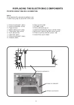
Presser foot lifter switch
Thread tension release lever
TO ENTER PRESSER FOOT LIFTER SWITCH ADJUSTING MODE:
Turn the power switch
on while simultaneously
pressing needle up/down
button and thread cutter
button.
Press the needle up/
down button within the 1.5
seconds to enter the self-
diagonostic mode.
The LCD will indicate “----”.
Press the 1 key.
Press the start/stop button four times to
enter the presser foot lifter switch mode.
Switch lever
Setscrew
Move the presser foot lifter switch.
Presser foot symbol
Summary of Contents for 5270QDC
Page 1: ...First Edition 06 March 2020 SERVICE MANUAL PARTS LIST MODEL 5270QDC For Europe only...
Page 39: ...37 TOUCH PANEL KEY POSITION ADJUSTMENT GUIDE Print this illustration guide to its actual size...
Page 52: ...50 MODEL 5270QDC PARTS LIST 1 2 3 4 6 5 7 8 9 10 11 12 13 14 17 15 18 19 20 9 21 21 22 23 16...


