21
DC4030P
SELF DIAGNOSTIC TESTS
CORRECT CONDITION
STEP
06)
Buttonhole
sensor
OPERATION
DEFECTIVE CONDITION
Press needle up/down button, LED
displays "06" for one second.
1. Lower the buttonhole lever.
2. Move the buttonhole lever back and
forth.
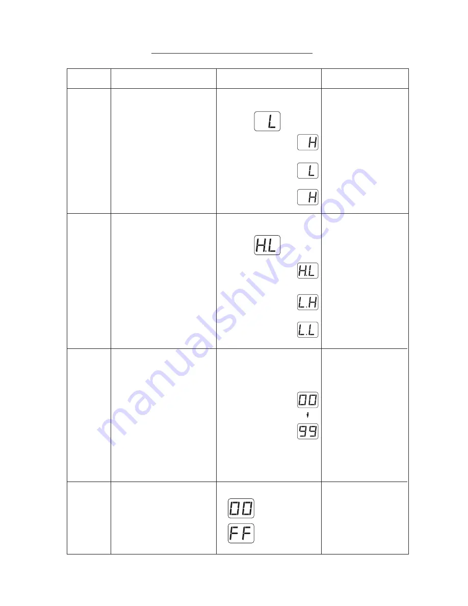
* LED indicates "L" or "H".
* When the buttonhole lever
is pulled, LED displays "H".
* When the buttonhole lever
is free (positioned in the
center), LED displays "L".
* When the buttonhole lever
is pushed, LED displays
"H".
LED display is different from
that shown to the left.
1. Adjust the buttonhole
sensor position.
2. Replace buttonhole
sensor.
3. Replace board "A".
07)
Upper shaft
sensor
Press the needle up/down button,
LED displays "07" for one second.
* Turn the handwheel toward you to
raise and lower the needle to its
highest and lowest position.
* LED indicates "H.L".
* When the needle is at
the highest position,
LED displays "HL".
* When the needle is at
the lowest position,
LED displays "LH".
* When the needle is halfway,
LED displays "LL".
* LED display is different from
that shown to the left.
1. Adjust upper shaft shield
plate.
2. Replace upper shaft sensor.
3. Replace board "A".
08)
Sewing
speed
sensor
* Press the needle up/down button.
LED displays "08" for one second.
* Turn the handwheel clockwise by
hand and check the counter value
displayed.
* LED displays "00" first and the indi-
cates value increases as you turn the
handwheel.
(When the value
reaches 100, it will
return to "00" and one
mode LED lights up.
For example, 2 mode
LEDs and "78" means
"278".)
The maximum value
should be 370 to 390.
* LED displays different from
that shown to the left.
1. Replace motor.
2. Replace board "A".
LED
LED
09)
Slide
volume
* Press the needle up/down button.
LED displays "09" for one second.
* Slide the speed control lever from the
left to the right, then return it to the
left.
* LED indicates "00".
(At left position)
(At right position)
* LED display is different from
that shown to the left.
1. Replace slide volume.
2. Replace board "A".


