19
Mechanical adjustment
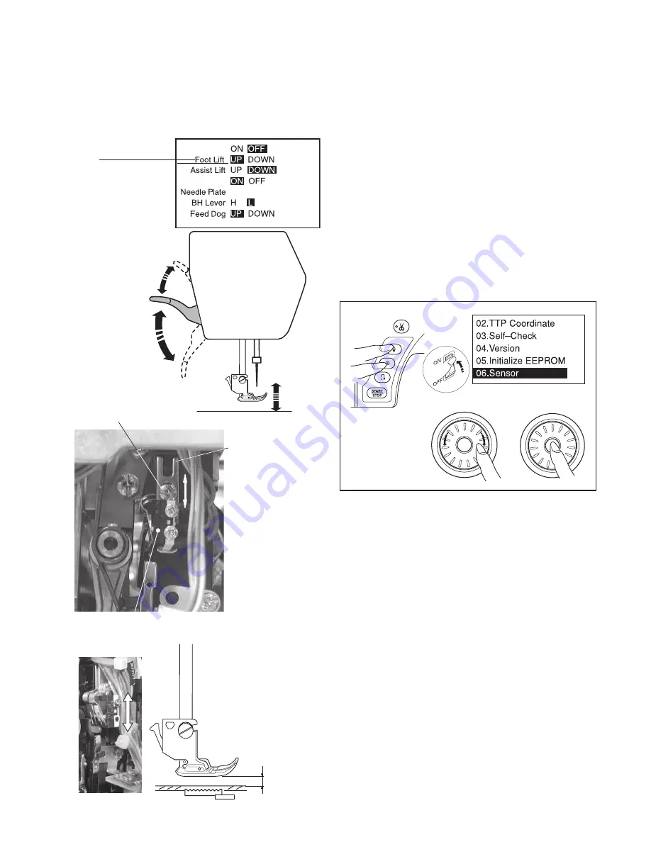
Presser bar lifter switch position adjustment
PRESSER BAR LIFTER SWITCH
Setscrew A
4 – 5.5 mm
Presser foot lifter
switch
Normal up
position
Extra lifted position
Lowered position
SWITCH SET PLATE
To check:
1. While pressing the needle up/down and lock stitch
buttons, turn the power switch on.
2. Turn the jog dial to select "06. Sensor".
Press the confirm button.
3. Remove the top cover (see page 1).
4. When the presser bar is at normal up position, the
"Foot Lift" shows "UP".
When the presser bar is at lowered position, the "foot
lifter" shows "DOWN".
When the presser bar is at the extra lifted position, the
"Assist lift" shows "UP".
When the presser bar is at normal position, the "Assist
lift" shows "DOWN".
If not, follow the procedure below.
To adjust:
1. Loosen the setscrew A and adjust the position of the
switch set plate.
The clearance between the foot and needle plate
should be in the range of 4 to 5.5 mm when the "foot
lifter" changes "UP" to "DOWN".
2. Turn off the power switch.
3. Attach the top cover plate and face cover.
Bobbin
Remote Cut
ZZ Plate


