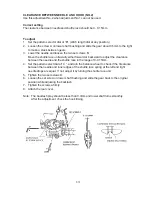
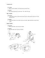
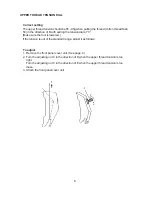
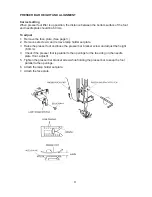
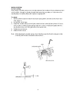
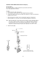
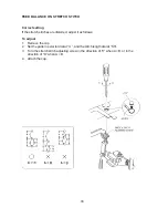
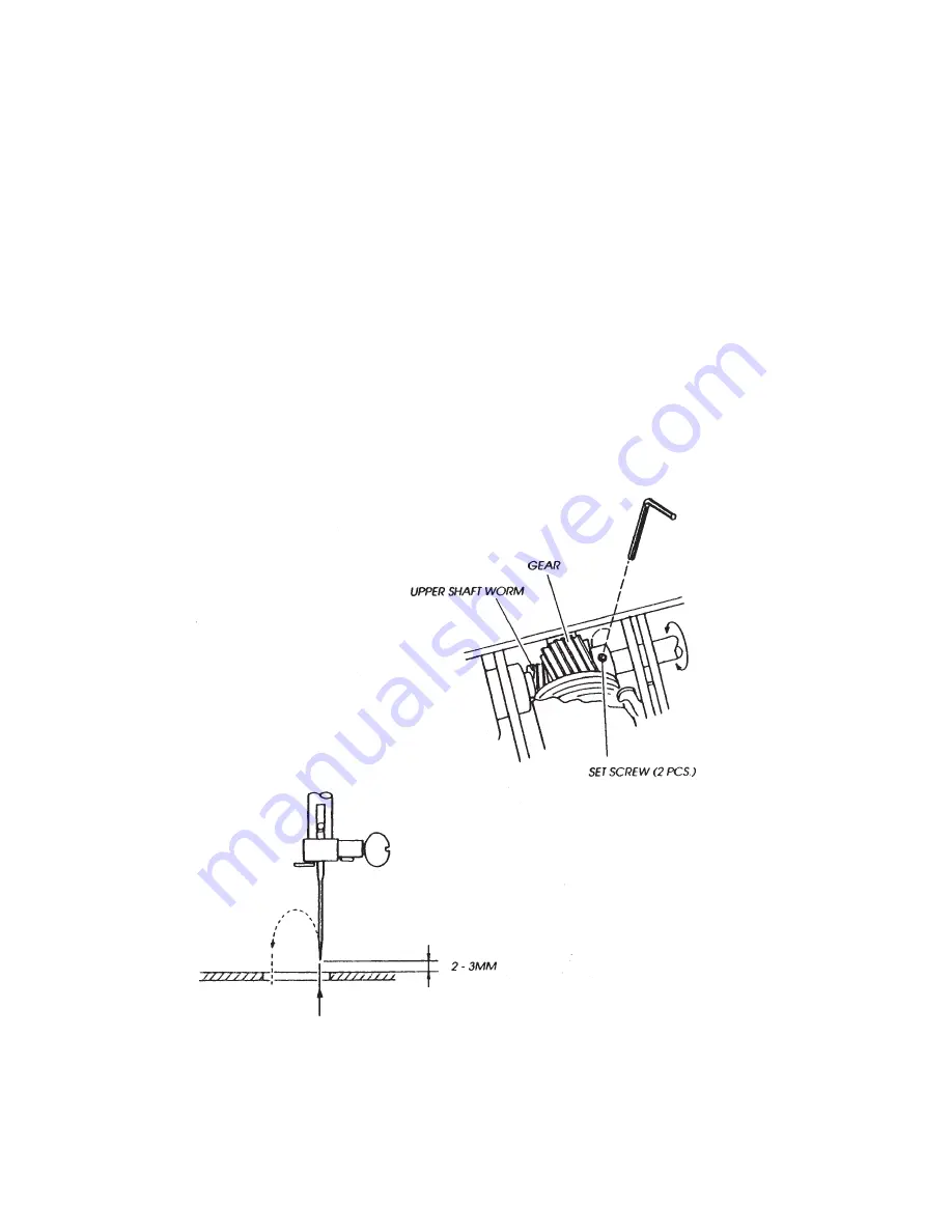
background image

9

NEEDLE SWING
Correct setting

If the timing of needle swing is not correctly adjusted, the needle will move sidewise while it
is in the fabric.  Ideally the needle should start swing from a position 2- 3 mm above the
needle plate in its right outflow with maximum zigzag width.
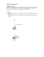
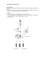
To adjust

1.

Set the pattern selector dial with maximum zigzag width, and remove the front cover.
(See page 4.)

2.

Loosen two set screws.

3.

Adjust the needle swing by turning the balance wheel, while pressing the worm so as
not to rotate it, until the needle swing starts at 2 - 3mm on the Needle plate after the
needle has come out of the right side of the needle hole.

4.

Tighten two set screws.

5.

Attach the front cover.

Note: After adjusting the needle swing, check that the upper shaft worm and gear rotate

smoothly with minimum backlash between them.

Summary of Contents for JF1018S

Page 1: ...SERVICING MANUAL Model JF1018S...

Page 2: ...Presser bar height and alignment 8 Needle swing 9 Needle drop 10 Height of feed dog 11 Clearance between needle and hook No 1 12 Clearance between needle and hook No 2 13 Needle bar height 14 Hook ti...

Page 3: ...stuck inside the bobbin holder 4 Thread quality is too low 5 Thread is jamming around the bobbin 6 Bobbin thread tension is too strong HOW TO FIX Insert the needle properly Change the needle Rethread...

Page 4: ...strong 4 Inappropriate feed balance CONDITION 5 Needle breaks 6 Noisy operation 7 Deformation pattern HOW TO FIX See mechanical adjustment needle drop Change the needle See mechanical adjustment Clea...

Page 5: ...cap BELT COVER To remove 1 Loosen the set screw and remove the belt cover by removing the belt cover rib from the front cover To attach 2 Attach the belt cover rib to the front cover And then Attach t...

Page 6: ...face plate and belt cover See page 4 2 Remove selector dials A and B 3 Loosen set screws C D E Ff G and then remove the front cover by removing set screws H I and J To attach 4 Attach the front cover...

Page 7: ...Remove the set screws C D E F and G 4 Pull up the 2 spool pins I and J and lower the presser foot lifter K 5 While pushing the rear cover l near the notches L and M pull upper part of the rear cover...

Page 8: ...dial at 3 Make sure the foot is lowered If the tension is out of the standard range adjust it as follows To adjust 1 Remove the front panel cover unit See page 4 2 Turn the adjusting nut C in the dire...

Page 9: ...bobbin thread tension should be 45 55g when pulling the thread in the direction of B If the tension is out of the range adjust it as follows To adjust 1 Turn the adjusting screw C in the direction of...

Page 10: ...emove set screw A and remove lamp holder set plate 3 Raise the presser foot and loose the presser bar bracket screw and adjust the height 6 0mm 4 Check if the presser foot is parallel to the openings...

Page 11: ...ctor dial with maximum zigzag width and remove the front cover See page 4 2 Loosen two set screws 3 Adjust the needle swing by turning the balance wheel while pressing the worm so as not to rotate it...

Page 12: ...e needle drop positions should be equal If not Make adjustment as follows To adjust 1 Remove the face plate See page 3 2 Set the pattern selector dial at maximum zigzag width 3 Loosen the set screw 4...

Page 13: ...If it is not in the range make adjustment as follows To adjust 1 Set the stitch length dial at 4 pattern select dial at any position 2 Lower the presser foot and turn the balance wheel until the feed...

Page 14: ...r to arrows to get clearance between 0 and 0 15mm When clearance is too wide move the needle bar supporter to direction B When clearance is too narrow move the needle bar supporter to direction C Note...

Page 15: ...ard or backward to adjust the clearance between the needle and the shuttle race in the range of 0 0 15mm 4 Set the pattern select dial at C and turn the balance wheel to check if the Clearance between...

Page 16: ...n To adjust 1 Remove the face plate See page 3 2 Set the pattern selector dial at B stitch length dial at any position 3 Remove the shuttle race ring 4 Turn the balance wheel toward you until tip of s...

Page 17: ...d you until the tip of shuttle hook meets the left side of needle 6 Loosen the set screws A 7 While holding the shuttle hook not to turn turn the balance wheel toward you until the needle comes to its...

Page 18: ...stitches are distorted adjust it as follows To adjust 1 Remove the cap 2 Set the pattern selector dial at A and the stitch length dial at SS 3 Turn the stretch stitch adjusting screw in the direction...

Page 19: ...es in the right side row backward feeding against 10 stitches in the left side row forward feeding is considered acceptable To adjust 1 Check the stitches by sewing buttonholes and remove the cap 2 Tu...

Page 20: ...ttern selector dial at and the stitch length dial at 4 2 Remove the front cover See page 4 3 Place a piece of paper under the foot and turn the balance wheel If the paper is fed forward turn the adjus...

Page 21: ...follower onto the top convex of the zigzag cam 4 Loosen the set screw 5 Push the convex part of the cam follower releasing arm in the direction of arrow until the cam follower releasing arm touches t...

Page 22: ...ger than the length set by the foot R To adjust 1 Remove the face plate See page 3 2 Turn the adjusting screw in the direction of A if the buttonhole stitch length is longer than the standard or in th...

Page 23: ...elt tension may cause jumping of the belt teeth on the motor pulley The correct motor belt tension is that the deflection of motor belt is about 7 mm 0 28 to 9 mm 0 36 when pushing the motor belt by f...

Page 24: ...22 WIRING...

Reviews: