


17
MECHANICAL ADJUSTMENT
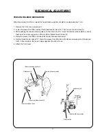
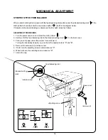
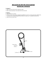
TENSION RELEASE MECHANISM
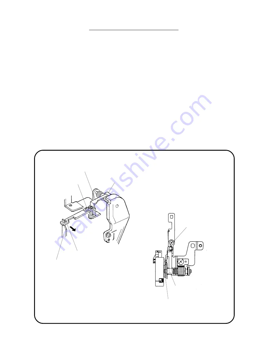
When the presser foot lifter is raised, the tension disk supporter should move approximately 1 mm.
1. Remove the front cover (see page 7).
2. Lower the presser foot lifter, and set the thread tension dial at "9". Then loosen the set screw (A).
3. While pushing the tension release plate (2) in the direction of "A", move the tension release plate (1) until it
touches tension disk supporter. In this condition, tighten the set screw (A).
4. Raise the presser foot lifter, and check the tension release mechanism.
5. Set the thread tension dial at "0". Lower the presser foot lifter. Move the tension release plate (2) back and
forth. In this condition, the tension disk supporter should not move.
6. Attach the front cover.
Setscrew (A)
Tension release plate (1)
Tension disk supporter
Tension release plate (2)
Tension release lever
Setscrew (A)
Tension disk
Tension disk supporter


