
49
MC 11000
7
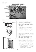
Adjusting the Microswitch
(1) Adjustment of lower stop position of LCD
Match the top side of the LCD unit with the upper
surface of the front cover by turnng the LCD motor
gear with finger.(Fig. 4)
Loosen the screw (E) and adjust the position of
the micro switch (2), so it turns on, then tighten the
screw.
(2) Adjustment of upper stop position of LCD
Match the bottom side of the LCD unit with the
lower surface of the front cover by turnng the
LCD motor gear with finger.(Fig. 4)
Loosen the screw (D) and adjust the position of
the micro switch (1), so it turns on, then tighten the
screw.
8
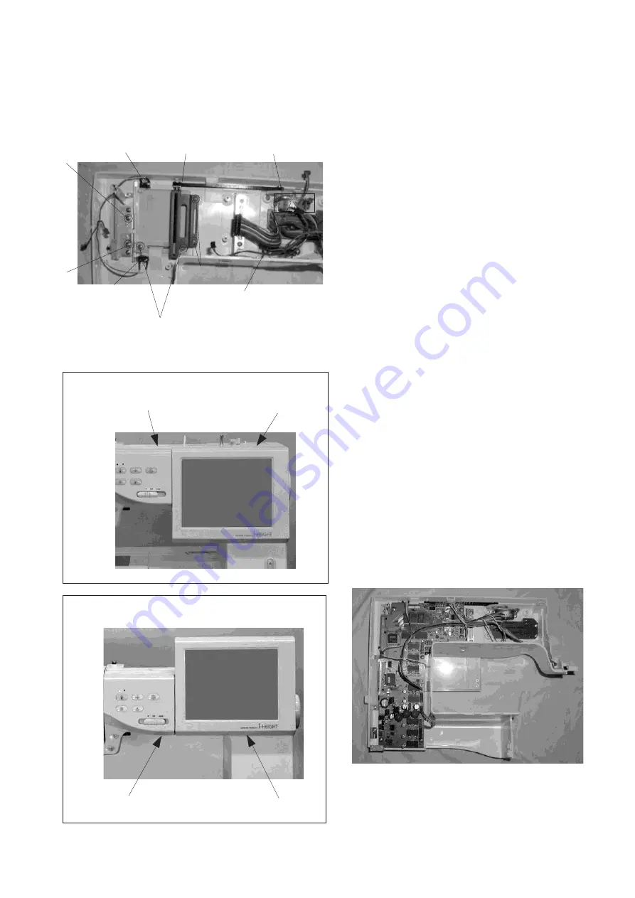
Attach the circuit board A.
9
Connect the each cord.
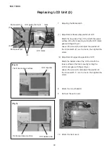
10 Attach the front cover.
Replacing LCD Unit (3)
(Fig. 5)
Front cover lower surface
(Fig. 4)
Gear
Micro switch(2)
Micro switch(1)
LCD motor
LCD guide shaft unit
(A)
(A)
(E)
(D)
Front cover upper surface
LCD top side
LCD bottom side


