16
200 g pressure
5 mm
Setscrew
Replacing electronic components
Driving motor
To remove:
1. Remove the belt cover, the top cover, the front cover and
auxiliary power supply unit case
(see page 1, 2, 5 and 13).
2. Disconnect the connector of the foot control from the
printed circuti board A (see page 7).
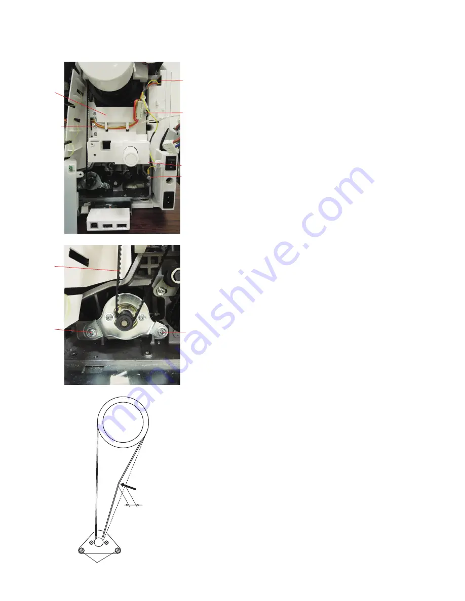
3. Disconnect the connector A from the power supply unit.
Remove the setscrew C and the ground wire.
Remove the setscrews B (3 pcs.) and the case D.
D
B
C
B
A
E
F
F
4. Disconnect the driving motor connecter from the printed
circuit board A.
5. Remove the motor belt E.
6. Remove the setscrews F (2 pcs), and the driving motor.
To attach:
1. Attach the driving motor.
Tighten the setscrews F temporarily.
2. Adjust the motor belt deflection to about 5 mm by
pressing the middle of the motor belt with your finger with
approximately 200 grams of pressure.
3. Tighten the setscrews F securely.
4. Attach the driving motor connector and the foot control
connector to the printed circuit board A.
5. Attach the case D with the setscrews B.
Be careful not to bind the cords with the cover.
Attach the connector A to the power supply unit.
Attach the ground wire with the setscrew C.
B


