11
Driving motor
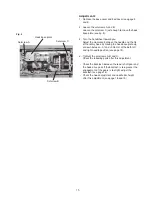
To remove:
1. Remove the belt cover and the base plate (see pages
1 and 3).
2. Loosen the setscrew A and remove the cord guide
plate (see fig. 1).
3. Disconnect the DC motor connector from the printed
circuit board A (see page 8).
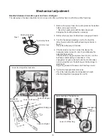
4. Remove the setscrews B, and the DC motor (see fig. 2).
Replacing electronic components
To attach:
1. Attach the driving motor. Tighten the setscrews
temporarily.
2. Adjust the motor belt deflection to about 5 mm by
pressing the middle of the motor belt with
approximately 200 grams of pressure.
3. Tighten the setscrews B securely.
4. Plug the driving motor connector to the printed circuit
board A.
5. Attach the base plate and the belt cover (see pages 1,
2 and 6).
Fig. 1
Fig. 2
Setscrew A
Cord guide plate
DC motor
connector
DC motor
Setscrew B
Motor belt
200 g pressure
5 mm
Setscrew


