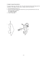
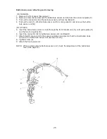

Multiple language function
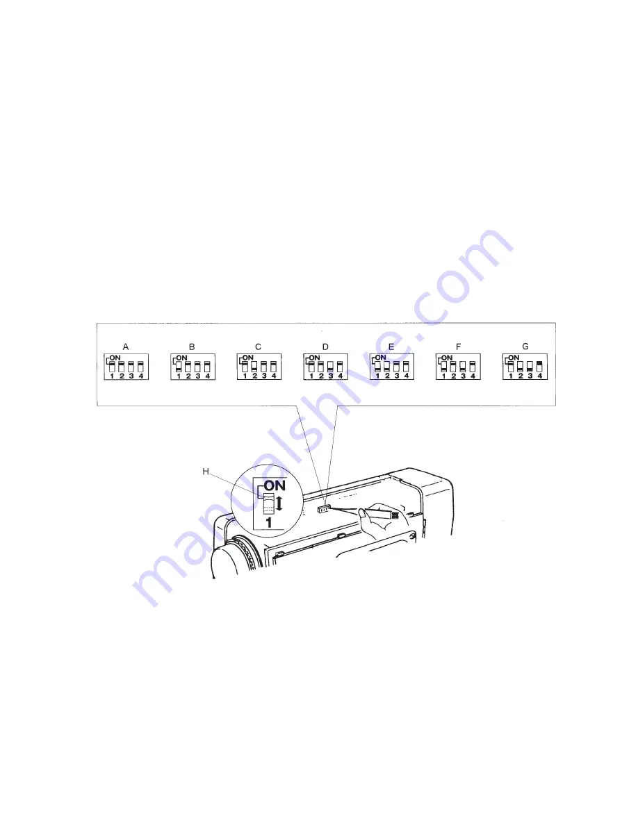
The display language can be changed if necessary, as illustrated bellow.
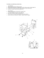
1.
Remove the top cover unit.
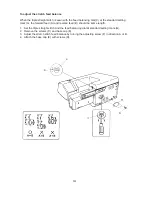
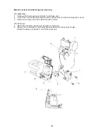
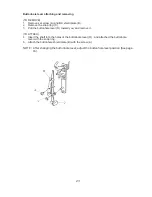
2.
Move the dip switches with the tail of the lint brush
A:
English
B:
Deutsch (German)
C:
Espanol (Spanish)
D:
Nederlands (Dutch)
E:
Francais (French)
F:
Italiano (Italian)
G: Portuguese
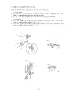
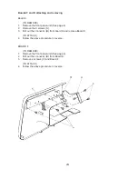
3.
Replace the top cover unit after adjustment.
27
Summary of Contents for Memory Craft 3000
Page 1: ...SERVICE MANUAL...


