15
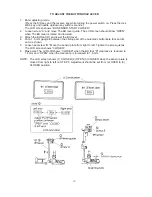
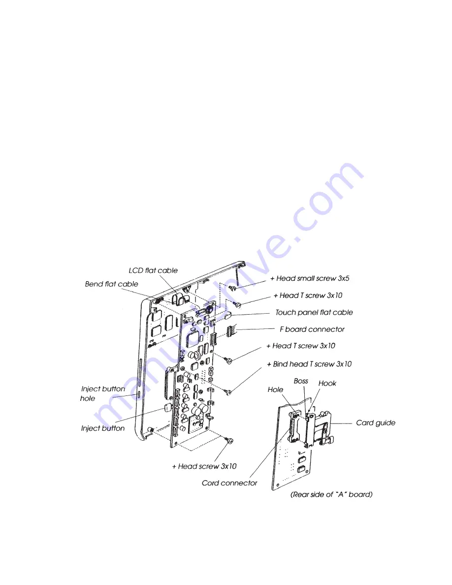
TO CHANGE PRINTED CIRCUIT BOARD
(“A” BOARD UNIT) 2
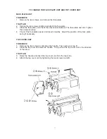
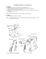
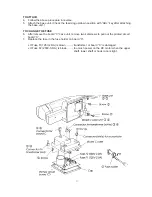
TO REMOVE
1.
Remove front panel (see page 14).
2.
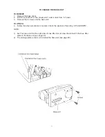
Disconnect the LCD and the touch panel flat cable and “F” board connector from “A” board
unit.
3.
Remove 6 screws to disconnect the printed circuit board “A” and card guide.
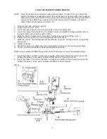
TO ATTACH
4.
Insert the card guide boss to the rounded hole of card connector until connected. Then
attach to “A” board.
5.
Attach the printed circuit board “A” with 6 screws and insert the 2 flat cables to the
connector, then push down the clamp.
(Make sure the inject button should be positioned at the front cover hole.)
6.
Connect “F” board.
7.
Attach the front panel unit.
NOTE: Adjust the (adjustment of touch panel) when the printed circuit board “A” is changed.
Do not touch the connecting part of the flat cable with your finger:
LCD flat cable should be inserted between the “A board unit and LCD board as shown
below.
Summary of Contents for MEMORY CRAFT 9000
Page 1: ...1 SERVICING MANUAL...


