15
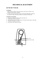
MECHANICAL ADJUSTMENT
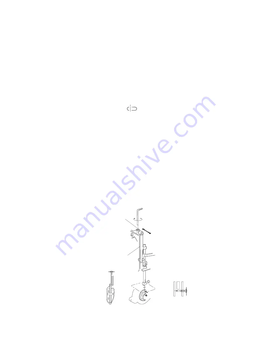
CLEARANCE BETWEEN NEEDLE AND SHUTTLE
(ADJUSTMENT METHOD NO. 1)
TO CHECk:
thE clEarancE BEtwEEn thE nEEdlE and ShuttlE racE Should BE –0.05 to +0.10 mm.
if not, adjuSt aS followS:
ADJUSTMENT PROCEDURE:
1. rEmovE thE facE covEr (SEE pagE 6).
2. SEt thE pattErn SElEctor dial at " ".
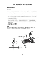
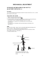
3. looSEn ScrEw (a), and movE thE nEEdlE Bar SupportEr in thE dirEction of
thE arrowS to gEt a clEarancE BEtwEEn –0.05 to +0.10 mm.
* if clEarancE iS too widE, movE thE nEEdlE Bar SupportEr in thE
dirEction (B).
* if clEarancE iS too narrow, movE thE nEEdlE Bar SupportEr in thE
dirEction (c).
NOTE:
aftEr thiS adjuStmEnt, chEck that thE clEarancE BEtwEEn thE nEEdlE and
nEEdlE platE iS 0.15 mm or morE aS Shown in figurE (d).
if not, adjuSt thE clEarancE BEtwEEn nEEdlE and ShuttlE racE BY uSing
adjuStmEnt mEthod no. 2 (SEE pagE 16).
4. attach thE facE covEr.
ScrEw (a)
dirEction (c)
dirEction (B)
nEEdlE Bar SupportEr
–0.05 to +0.10 mm
figurE (d)
clEarancE BEtwEEn nEEdlE and
nEEdlE platE Should BE 0.15 mm or
morE.
Summary of Contents for NH15
Page 1: ...1 SERVICE MANUAL MODEL NH15 PARTS LIST...
Page 23: ...23 WIRING 1 WIRING FOR MACHINE SOCKET UNIT L M M MOTOR L LAMP M L 120V 240V...
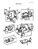
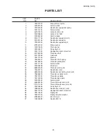
Page 34: ...34 MODEL NH15 PARTS LIST 1 2 3 4 4 5 6 7 8 9 10 11 12 13 14 8 4 15 16 17 8 8 18 19...
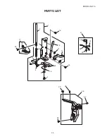
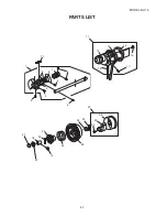
Page 38: ...38 MODEL NH15 PARTS LIST 1 2 3 9 5 8 6 7 4...
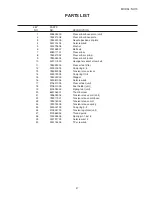
Page 40: ...40 MODEL NH15 PARTS LIST 2 8 1 4 5 7 6 3 9 10 11...

