16
MECHANICAL ADJUSTMENT
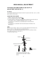
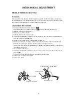
CLEARANCE BETWEEN NEEDLE AND SHUTTLE
(ADJUSTMENT METHOD NO.2)
TO CHECk:
uSE thiS adjuStmEnt mEthod no. 2 if thE clEarancE cannot BE adjuStEd
BY mEthod no.1.
thE clEarancE BEtwEEn thE nEEdlE and ShuttlE racE Should BE –0.05
to +0.10 mm.
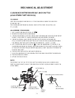
ADJUSTMENT PROCEDURE:
1. SEt thE pattErn SElEctor dial at " ".
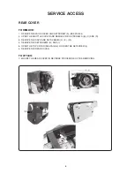
2. rEmovE thE rEar covEr (SEE pagE 8).
3. looSEn thE ScrEw (a) on thE lowEr Shaft BuShing and SlidE thE gEar aBout
0.5 mm to thE right to crEatE SomE BacklaSh BEtwEEn thE gEarS.
4. lowEr thE nEEdlE and looSEn thE two ShuttlE racE SEtScrEwS (B).
pull up or puSh down thE ShuttlE racE to adjuSt thE clEarancE BEtwEEn
thE nEEdlE and thE ShuttlE racE in thE rangE of – 0.05 to + 0.10 mm.
5. SEt thE pattErn SElEctor dial at " ", turn thE handwhEEl to chEck if thE
clEarancE BEtwEEn thE nEEdlE and innEr EdgES of thE ShuttlE racE Spring
at thE lEft and right nEEdlE dropS arE Equal. if not, adjuSt BY turning thE
ShuttlE racE unit.
6. tightEn thE two ShuttlE racE SEtScrEwS (B).
7. SlidE thE gEar Back to thE original poSition whilE adjuSting thE BacklaSh.
8. tightEn ScrEw (a) firmlY.
9. attach thE rEar covEr.
NOTE:
thE rotarY plaY of thE tip of thE ShuttlE drivEr Should BE 0.3 mm or lESS
and thE lowEr Shaft Should turn SmoothlY. aftEr thE adjuStmEnt, chEck thE
hook timing.
–0.05 to +0.10 mm
clEarancE Should BE Equal
ShuttlE racE
SEtScrEwS (B) (2)
lowEr Shaft
BuShing (front)
nEEdlE
ShuttlE
racE Spring
SEtScrEw (a)
lowEr
Shaft
BoSS
Summary of Contents for NH15
Page 1: ...1 SERVICE MANUAL MODEL NH15 PARTS LIST...
Page 23: ...23 WIRING 1 WIRING FOR MACHINE SOCKET UNIT L M M MOTOR L LAMP M L 120V 240V...
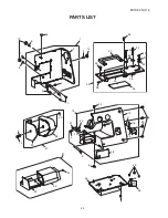
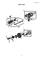
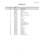
Page 34: ...34 MODEL NH15 PARTS LIST 1 2 3 4 4 5 6 7 8 9 10 11 12 13 14 8 4 15 16 17 8 8 18 19...
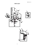
Page 38: ...38 MODEL NH15 PARTS LIST 1 2 3 9 5 8 6 7 4...
Page 40: ...40 MODEL NH15 PARTS LIST 2 8 1 4 5 7 6 3 9 10 11...

